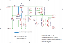
Thanks for the replies. Attached is the circuit I will be using.Sorry I am so dumb, but i still do not understand how to calculate the value of R1.
Thanks
Alan.
This one will blow Q2 if with 50V+ Vin. Exchange Q2 & R3 for a 10K 1W. R1 sets the current by Ohm's law when dividing the difference of voltage across 3 Leds and Mosfet's Vgs (voltage across gate and source pins). Its like in DCB1, 10 Ohm should give between 160 and 200mA depending on Leds and MOSFET. Start with 6.8R 2W resistor and red generic LEDS for 250mA you mentioned. The voltage drop across the resistor divided by 6.8 will give you the exact current in your build.
Thank you Salas, I now understand how to calculate R1. Is there any other FET that I could use in place of the Q2 2SK170, as I think I have read in one of your posts that using a transistor in that position made an audable improvement over using a resistor. I will of course follow whatever you recomend.
Many thanks
Alan
Many thanks
Alan
You may use a ring of two CCS at 5mA with 60V transistors at the LEDs tail, I have shown such examples before. The 10K is the simplest substitution because K170 is 40V only.
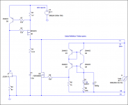
Reflektor +1.2V
I have been evaluated in a few days, and decided to optimize Zobel.
Old; 0R47+0.44uF New; 0R2+2.2uF
As a result the sound became more smooth, transparent without stress. Space is fully filled with music. Of course it is stable strongly. I am satisfied.
Now I noticed on one principle foolishly.
In the Bode chart, if Zobel is optimized rightly, the gain and phase of output are changing smoothly beyond audio frequency zone.
Salas, is it correct?
Attachments
Yes its true. Still it has to do with possible load oddities too. So there is safer general termination or optimized. You could end up to something bit different in another DAC for instance. Checking stability with your scope is the first testing principle when making changes as you have mentioned.
In my experiments with the reflekor I also found 2uF better than 0.47u in the output zobel.... Of course I was powering a simplistic and not a DAC so results are system dependent.I have been evaluated in a few days, and decided to optimize Zobel.
Old; 0R47+0.44uF New; 0R2+2.2uF
As a result the sound became more smooth, transparent without stress. Space is fully filled with music. Of course it is stable strongly. I am satisfied.
I wonder if it's possible to use the salas regulator as a filament dc supply.
What's available is 7.5v ac and that is supposed to end up as
4,75-5,25v dc @1,8A.
Is this possible and how much ac ripple is there to be expected at the output ?
What's available is 7.5v ac and that is supposed to end up as
4,75-5,25v dc @1,8A.
Is this possible and how much ac ripple is there to be expected at the output ?
Last edited:
I wonder if it's possible to use the salas regulator as a filament dc supply.
What's available is 7.5v ac and that is supposed to end up as
4,75-5,25v dc @1,8A.
Is this possible and how much ac ripple is there to be expected at the output ?
It has been done for heaters using a basic V1 special with low Vbe power BJT output by member disco for a #26 preamp down to 1.5V.
You would need a heavy PMOSFET in the CCS basically, and the lower impedance MOSFET output versions are still OK for your circa 5V. Don't ask for sure ripple numbers, we haven't used a config as you describe before. You may try a Reflektor with IRF9640 at CCS and STP55NF06L at output. ICCS=Vbe/R1. Set 2A+. Watch CCS MOSFET's dissipation, it will be around 10W.
what Is and what for reflector Is used
Its a regulator mixing shunt current sinking and current mirror control principles. Its used for powering various circuits with rather nice subjective results.
hi, if I want to build the +30V shunt reg on proto matrix board, and not the most complicated one, which version would you recommend ?
You would not find it exactly, I just set it for you. Use 1W R1. M2 is an easy to get Fairchild, but you can use ST Micro STP55NF06 too. Analogous.
P.S. you can trim R6 with adding some little more value to it for 30V sharp if it ends up less than target, depends on your semis bias. Better than a trimmer.
... Here is your asked example. Good luck.
schematic says +40Vdc input, which is fine
but is there any 'slack' on that, plus minus a few volt maybe, or any specific limits ?
- Status
- Not open for further replies.
- Home
- Amplifiers
- Power Supplies
- The simplistic Salas low voltage shunt regulator