I would not call it sinusoidal it looks like a big hump that gets smaller in 5-6 steps and then starts over. Around 1.6MHz. Anything I can do without making new pcbs?
Try make the 27R higher value maybe you will luck out and won't resort to positional experiments.
Try make the 27R higher value maybe you will luck out and won't resort to positional experiments.
No luck, tried 220R and 1k, same shape and amplitude as before.
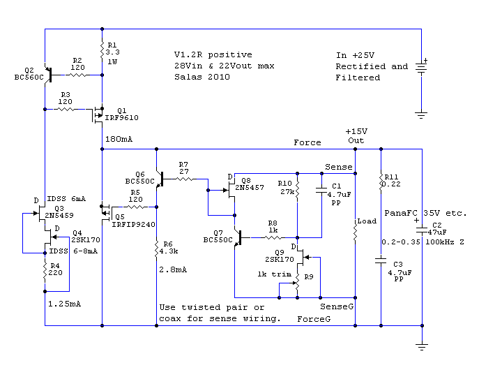
Is R8 tightly near Q7's base with minute leg length? Maybe there is room for improvement there? Also, can you catch that gremlin originating at the input CCS section?
Is R8 tightly near Q7's base with minute leg length? Maybe there is room for improvement there? Also, can you catch that gremlin originating at the input CCS section?
R9 is 1cm from Q6's base. R10 is closer than 0.5cm from Q7's base. I'll measure some more a bit later to see if I get from where it comes.
R8 first schematic or R10 3rd schematic. Get it even closer to base with minimal leg when you can. But see first if it comes from earlier stage so to focus the problem. If the LED isn't healthily bright (1-2mA bright) there is hint from main CCS.
If coupling between leads is an issue perhaps you could slide a grounded piece of foil between the interfering leads. A piece of foil attached to ground with an alligator clip could be a sort of probe. Some dead electronics have plastic laminated copper foil that would work perfectly for this.
Hi Salas
Could you help me, please.
I'm building L'Amp
.......
Grazie mille
Marco
OK, will investigate and reply you a circuit.
Here is your circuit. Get some Toshiba 2SK117GR, measure their IDSS. Use just a little above 3mA for J3, pick from lowest IDSS group in your batch for J1, and from highest for J2. For C2 get one with about 0.3 Ohm ESR. For C1 the best electrolytic you like subjectively. M1 is going to dissipate around 14W, M2 around 6W. Don't test without 2A load, in that case M2 is going to burn 55W!
Attachments
Here is your circuit. Get some Toshiba 2SK117GR, measure their IDSS. Use just a little above 3mA for J3, pick from lowest IDSS group in your batch for J1, and from highest for J2. For C2 get one with about 0.3 Ohm ESR. For C1 the best electrolytic you like subjectively. M1 is going to dissipate around 14W, M2 around 6W. Don't test without 2A load, in that case M2 is going to burn 55W!
Salas
Thank you very much!!
Some questions:
Flter capacitor, it'ok 10KuF ?
Diode, i have Ixis soft recovery 10A/1000V , are good?
And last, dummy load, 10R 30W it's suffice?
Marco
Salas
Thank you very much!!
Some questions:
Flter capacitor, it'ok 10KuF ?
Diode, i have Ixis soft recovery 10A/1000V , are good?
And last, dummy load, 10R 30W it's suffice?
Marco
At that current 10mF//10mF is better so to divide ESR and up the ripple current rating. Diode you got OK, but sink it. 12R 50W on sink dummy or the amp itself.
hello, just built version 1.2r for my dac...
for sure i'm missing something.. everything works fine with dummy load (1k 10w), connected to real load, Buffalo III, trimmer (1k) stops regulating and Vout is blocked at 3,9v...
R1 is 1 ohm, current output is +/- 650mA, Vin is +/- 16V
scheme is this one:

should i lower R11 to ... let's say 10k to have proper behaviour??
of course triple checked all connections 😛
any help will be very appreciated!!
for sure i'm missing something.. everything works fine with dummy load (1k 10w), connected to real load, Buffalo III, trimmer (1k) stops regulating and Vout is blocked at 3,9v...
R1 is 1 ohm, current output is +/- 650mA, Vin is +/- 16V
scheme is this one:

should i lower R11 to ... let's say 10k to have proper behaviour??
of course triple checked all connections 😛
any help will be very appreciated!!
Blocked at 3.9V spells VGS so Q5 works. One thing is you tested it at very low mA with 1k load. What exactly is your target output voltage and consumption when you got 16V in?
1.1 was but ended. Ask Tea-bag, I think he said it will take him 3 months or so to put out a few again.
my target is 5v output @500mA, perhaps 11v Vdrop is too much?Blocked at 3.9V spells VGS so Q5 works. One thing is you tested it at very low mA with 1k load. What exactly is your target output voltage and consumption when you got 16V in?
what i don't get it is why it works with dummy load...
just to be sure.. for a proper simulation of the load it's ok to use a 10ohm resistor?? 5v/500mA gives a 10r resistor...
If you haven't checked the actual voltage drop across R1 and then divide by its value, its possible it does not really run that much current and the real client circuit brought it to its knees. Your dummy was quite light for ''prova generale''. Yes a 10R dummy would be much more representative of feeding the buffalo. A 10W one spare from building loudspeakers maybe. 11V drop creates heat but no obstacle.
- Status
- Not open for further replies.
- Home
- Amplifiers
- Power Supplies
- The simplistic Salas low voltage shunt regulator
