In the SIT rush, I bought few 2SK182ES bought and have been thinking what to do with them.
I wish I could win a Pass Vfet kit but came with empty hand, so decided build a simple one with the devices I have.
A post was done before and got all helps from our member including Mr. Pass. So I come with the original simple way.
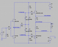
It is like F4, the famous Jfet buffer with DEFiSIT. The bias is very simple: two diodes.
After I did sim I like to start with heavily degenerated Mosfet, like one our member suggested.
I wish I could win a Pass Vfet kit but came with empty hand, so decided build a simple one with the devices I have.
A post was done before and got all helps from our member including Mr. Pass. So I come with the original simple way.
It is like F4, the famous Jfet buffer with DEFiSIT. The bias is very simple: two diodes.
After I did sim I like to start with heavily degenerated Mosfet, like one our member suggested.
Attachments
Selection of Mosfet
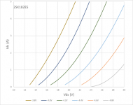
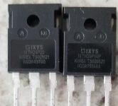
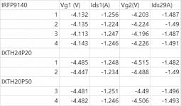
After some search and found IXTH24P20 and IXTH20P50 may suitable to the SIT I have. The hope is larger Vgs at Ids about 1.5A.
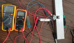
Setup a small fixture to test them, the testing was done with elevated temperature because of a small heat sink. It was luck to find all IXTH are close to the SIT to do a DEFiSIT.
Vgs of 9140 are to high at same conditions.
After some search and found IXTH24P20 and IXTH20P50 may suitable to the SIT I have. The hope is larger Vgs at Ids about 1.5A.
Setup a small fixture to test them, the testing was done with elevated temperature because of a small heat sink. It was luck to find all IXTH are close to the SIT to do a DEFiSIT.
Vgs of 9140 are to high at same conditions.
Attachments
Build
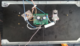
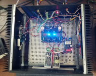
Since the circuit is very simple. Build Jfets and bias adjustment with a small testing board. Two diodes are mounted on opposite site so they are close to heat sink to have some temperature sensing.
Unlike other amplifier, there is no trimmer position for minimal Id. It is better to preset Vg for SIT and Mosfet before connecting SIT and Mosfet.
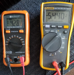
The procedure is like this: based on target Ic, estimate Vg for SIT, from the Vds-Ids-Vgs curve of the device, Id=1.5A, Vgs=-4.4V at Vds=24V, plus voltage loss on Rs, 0.11x1.5=0.165V, so set Vg for Sit is set around -4.25V by adjusting the trimmer. The Vg for Mosfet is preset automatically -4.25-1.2V=-5.45V
Since the circuit is very simple. Build Jfets and bias adjustment with a small testing board. Two diodes are mounted on opposite site so they are close to heat sink to have some temperature sensing.
Unlike other amplifier, there is no trimmer position for minimal Id. It is better to preset Vg for SIT and Mosfet before connecting SIT and Mosfet.
The procedure is like this: based on target Ic, estimate Vg for SIT, from the Vds-Ids-Vgs curve of the device, Id=1.5A, Vgs=-4.4V at Vds=24V, plus voltage loss on Rs, 0.11x1.5=0.165V, so set Vg for Sit is set around -4.25V by adjusting the trimmer. The Vg for Mosfet is preset automatically -4.25-1.2V=-5.45V
Attachments
Fine adjust and Burn in
The sole adjustment this circuit has is set the offset zero. To increase the Ids, both Rs have to be reduced or add more diode.
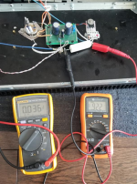
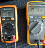
The Id and the offset after 3 hours The heatsink temperature is under 50°C, room temperature 25°C.
After another 2 hr playing music , the offset 4mV and the Id 1.29A
To simple to be true!
The sole adjustment this circuit has is set the offset zero. To increase the Ids, both Rs have to be reduced or add more diode.
The Id and the offset after 3 hours The heatsink temperature is under 50°C, room temperature 25°C.
After another 2 hr playing music , the offset 4mV and the Id 1.29A
To simple to be true!
Attachments
Great job and thanks so much for sharing! 
Do you plan on making another channel or was this strictly done as an exercise?
I've been very tempted to try this out but always chicken out. Thanks for the explanation. I may revisit this yet.
Do you plan on making another channel or was this strictly done as an exercise?
I've been very tempted to try this out but always chicken out. Thanks for the explanation. I may revisit this yet.
After reading about your efforts with the SMPS used to power your F4, it seems best to try this new design of yours with a linear power supply.
That is a nice, simple looking circuit. I bet it will sound great.
That is a nice, simple looking circuit. I bet it will sound great.
In my amp, the left channel is SIT and the right channel is F4. I am am listening mono SIT or mono F4 or stereo SIT-F4.
The initial feeling is positive. I will keep listening for few weeks and play with Ids and Rs.
The initial feeling is positive. I will keep listening for few weeks and play with Ids and Rs.
One of the areas where I find the performance of a power supply makes the most audible difference is in the stereo presentation. This remains the case with my Sony VFET amp and its new linear PSU. For the purpose of evaluating amplifier circuits and their interaction with the PSU, I suggest making both channels identical.
As I am well beyond my limited understanding here, can you please confirm that R6 is the trimmer you are using to adjust offset? Another question I have is on the source degeneration of both devices. I understand that you want to apply some compensation for less than a perfect match of devices for where you want the operating voltage and current to be but why do you have small amounts of degeneration on both sides? Isn't it only necessary on one and isn't it desirable to have zero source degeneration if possible?
You didn't mention if you had 2 SIT devices that are matched for 1.5A @24V so I guess you'd have to recalculate R8 and/or R2 to have the same current for the given rail voltages. It also looks like you are one of the lucky ones who has relatively high Idss SITs in the 4.5V range at 1.5A. Most of the SITs are in the 3.x and 2.x range from what I've seen.
Last question if I may ask - the 1.2V delta (-4.25-1.2 = -5.45V) - where is this derived from or why are you looking for 1.2V difference in Vgs? Is that the target Vgs to get the same current (1.5A @24V) through the mosfet?
Cheers!
Stephen
Last edited:
Yes. R6 is 30K+10K trimmer. Once you find the proper P-Mos for your SIT, everything becomes simple. You only need to play with Rs on the both device to get Id you want and sound you like.
Yes, Mr. Pass and Zen Mod showed the zero source degeneration is desired. In this case Mosfet will do heavy job and SIT works against it. You can check the Id curve of SIT and Mosfet in Sim without degeneration. It looks like SIT is kind of CCS for Mosfet.
I'd like SIT work harder and and do more work in amp(because we spent big money on it!). lhquam used heavy degeneration on Mosfet so both SIT and Mosfet can work together and not against each other. Also using a larger Rs on Mosfet side, the circuit leaves Class A much later. But the goal is not just get perfect circuit but the sound you like. I bough few big Rs from 0.22 to 1 ohm and will try more.
Also, I use SMPS for power supply. So the fluctuation of power network will have limited affect on the offset and Id (for asymmetric bias voltage) . Now I understood why Zen Mod wants to get symmetric +/- Vg bias for power transistors.
I like pure DEF principle, it's wakoo enough and I choose not to spoil it
probably exactly because of that, I declared that SIT is working as Error Correction for Mosfet

amps having symmetrical/complementary OS devices are easy/boring to make

probably exactly because of that, I declared that SIT is working as Error Correction for Mosfet
amps having symmetrical/complementary OS devices are easy/boring to make
Hello twitchie,
Thank you for your interest.
I didn't do sim with IXTH24P20 since I don't have the model. Instead I used 9240. Surprisingly, DC state in the sim is very close to my experiment(within 5%). For 2SK182ES, I got the curve from the seller.
Today, I shorted R8 and it is burning in and make bias adjustment.
Attachments

Last edited:
Thank you so much wwwtttwww!
Is it possible to post the .asc file? For the degeneration resistors, how many watts should these be rated for (ie, how much power goes through them)?
Is there any rough guidance on how much resistance to apply for a given difference between Vgs of SIT vs mosfet. For example in your case if you had a 1.2V difference and you applied (for example) 0.8R of degeneration ...
I'm oblivious to the math required to calculate this and I'm open to experimentation but would like to know that I have adequately rated resistors.
Thanks!
Stephen
- Home
- Amplifiers
- Pass Labs
- The simplest DEFiSIT with 2SK182ES