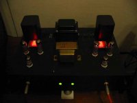
from the front... 😀
More pics of the other components (mostly DIY of course!) at
http://home-and-garden.webshots.com/album/557913608arvnpO
More pics of the other components (mostly DIY of course!) at
http://home-and-garden.webshots.com/album/557913608arvnpO
Attachments
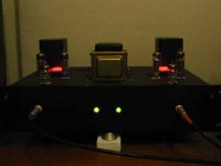
Well done, can you give us a photo with the light on of the top and underneath please. Did you find it easy? what part was the hardest? how about soldering all the leds together did you find that easy. Your thoughts and imressions please. What size is the chassis?
kopite said:Well done, can you give us a photo with the light on of the top and underneath please. Did you find it easy? what part was the hardest? how about soldering all the leds together did you find that easy. Your thoughts and imressions please. What size is the chassis?
No photos of the underneath, it's a big mess down there!

For me, the hardest part was to get the EL84s to bias at 85mA! It seems my tubes were biasing low. Thanks to SY's help and advice, I managed to get it up to 80+mA. Otherwise the rest is pretty OK for me. Solering the LEDs together on a prefboard, like SY did, is not all that difficult, you'll get the hang of it after a few. I like the sound, really got no complaints at all. Previously I've heard the sound from a EL84 in pentode, and it was slightly "unrefined", with regulated screens like the RLD, it's much smoother. No problems handling anything with my speakers. The chassis is about 12" by 9", recycled from a previous project.
Concertina B+ voltage
I have noticed that the Concertina phase splitter is supplied by 350V, requiring a higher B+ supply than the EL84.
Could you explain why this high voltage has been selected?
The EL84 will only require up to 22V p-p drive. I have understood that textbooks suggest that the maximum swing with Concertina is limited to 20% of supply voltage. This should have given plenty of margin even with a 300V (or even 250V) supply.
I am asking this as it is relevant to the possible use of Concertina in other applications - I am trying to learn.
I apologise if I have missed this point earlier in the tread, or in the article published.
SveinB.
Linearity, pure and simple. You have to look at the split load and the input stage together as a system. If you want to get a reasonable linearity from an ECC81 voltage amplifier at the full swing needed to drive the output stage, it needs 110-120V at least on its plate (lower and you hit the bunching of the curves and distortion rises). So that means that the direct-coupled split load will have to have a similar voltage (ignoring the couple volts of bias) on its cathode. Add the 110-120V cathode-to-plate, then another 110-120V for drop across the plate resistor and we've pretty quickly reached 350V or more.
JoshK,
All the LEDs are in series to get that 110V rating rather than the parallel combination of series strings required.
So:
Voltage is too high.
Current capability will be too low.
Pity but thats the way "the mop flops".
Cheers,
Ian
All the LEDs are in series to get that 110V rating rather than the parallel combination of series strings required.
So:
Voltage is too high.
Current capability will be too low.
Pity but thats the way "the mop flops".
Cheers,
Ian
You're right...guess I should have guessed that. Its too bad, because it would be nice to have an easy plug n play solution if one/many LEDs died. Oh well, it isn't hard to solder em up.
Buy one, take it apart, and see how the LEDs are attached. You might be able to extract and/or rewire them. If it looks do-able, take one out and see what its forward voltage and impedance are to determine feasibility. If it looks like it could work, that would be very cool. You can buy more.
For once, yes. I'm very curious about what those LEDs could be but waaaaay too backed up with to-do projects.
I had jokingly suggested to SY a long time ago to find a pair of Cadillac taillights for his next project. Whenever I see these massive LED arrays blinking in front of me at a stop light (itself an LED array...hmmm), I can’t help but think of audio. Sick, huh? But maybe the basic idea of using an existing LED lamp array is worth pursuing. I don’t suggest an expensive and silly-looking taillight (although the 13 to 14 volts they’re designed to run on is a lot closer to what an EL84 might need in the cathode). These 110 V screw-in lamps are certainly cheap enough to experiment with. The LEDs are bound to be in series, as Gingertube says, and they must be soldered into a PC card carrier that connects them at way. I doubt that there could be much “wiring” at this price. I wouldn’t be surprised to learn that there is also some current-limiting device in series. There is a clue in the ad about how they can be connected to twice the voltage (220V) although with shortened life. Maybe there’s just a series resistor to flatten the sharp knee? So you’d have to modify the PCB to convert it to series-parallel connection according to your audio voltage needed. And who knows if these LEDs have the sharp I-V knee that characterizes the low impedance LEDs? I thought I read in this forum (SY, you?) that the older red LEDs seemed to exhibit the lowest impedance.
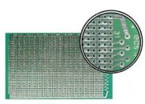
Keep an eye out for bags of cheap surplus single LEDs. I bought 500 red HP LEDs for $3 at a hamfest. I haven’t done it yet, but you could buy one of those common prototyping PC boards with copper-ringed holes placed on 0.1” centers. Simply solder the LEDs in rows and columns as needed, run a few bare wires along the columns, and there you go. I think this is what a few folks have already been doing here. Probably easier than modifying an existing lamp array, but still, for 6 or 10 bucks, pulling apart one of these lamps might be worthwhile.
Keep an eye out for bags of cheap surplus single LEDs. I bought 500 red HP LEDs for $3 at a hamfest. I haven’t done it yet, but you could buy one of those common prototyping PC boards with copper-ringed holes placed on 0.1” centers. Simply solder the LEDs in rows and columns as needed, run a few bare wires along the columns, and there you go. I think this is what a few folks have already been doing here. Probably easier than modifying an existing lamp array, but still, for 6 or 10 bucks, pulling apart one of these lamps might be worthwhile.
you could buy one of those common prototyping PC boards with copper-ringed holes placed on 0.1� centers.
There are also board with 3 holes per 'island', they are probably even easier to build the series/parallel LED array. See the picture.
Attachments
Giaime said:
I agree! We use them in our kits, a design loosely based on your circuit 😉 Zero microphonics, and very low distortion before applying feedback.
Btw, I can't understand how they connected pin 9 on them. I see 6.3V on it (I'm heating them with 12.6VDC between pins 4 and 5), so it must be the center tap of the heaters, but it appears to be connected to the shield between sections (as common frame grid tubes, es. ECC88).
Have you tried ECC83s and ECC803s from JJ/Tesla? I'm interested in opinions, especially in critical phono stage use. The standard ECC83s has plates like a frame grid tube, and it appears that this technique can further reduce noise and microphonics, very important in a phono amp.
Hi,
Sorry to disturb you guys but I've just been browsing through this thread and noticed Giaime's question:
Have you tried ECC83s and ECC803s from JJ/Tesla? I'm interested in opinions, especially in critical phono stage use. The standard ECC83s has plates like a frame grid tube, and it appears that this technique can further reduce noise and microphonics, very important in a phono amp.
This is a construction method that dates from the last years of tube development by Philips and TFK.
The purpose was to improve on the ECC83 in several ways, lowered microphony, lowered input capacitance, higher bandwidth and lowered noise.
You'll find the construction details with drawing of the specially wound grids and heaters, frame anchors etc. described in the Philips Laboratory editions. (good old phonebook size, you've been warned)
The reason Tesla is still using this construction is that they bought a lot of the TFK tooling way back when and this tube was quite in demand in the latest studio equipment from Studer-Revox to Nagra and a raft of other dedicated gizmos....
One type that's very similar and that I've used with great success in a phono stage was the E283CC from the same era as the similarly constructed E188CC, E288CC and the super low noise penthodes such as E180F and so on.
Those were the days when you saw incredibly specced electron tubes but not necessarily good sounding ones, read: too low even order harmonic distortion, no bloated lower mid, so don't expect that typical tube colouration some people kill for....
Again, sorry for the interruption....couldn't resist to shed some LED on this to be perfectly honest.😉
@SY, nice work young man, nice work....
Cheers, 😉
Thank you, Frank. I have some of their 12AX7s on hand and will (one day) get around to testing them against my old stock zoo.
Tweeker said:Speaking of LEDs and traffic control, those police LED lightbars are freaking blinding.
Ah, well, in that case there's no point in pinching one. You need the old-fashioned dim and dingy LEDs.
That's been a good rule of thumb, but the dimmest ones I have on hand measured the worst (about 10R at 10mA). I've tried some extremely bright Agilent LEDs of current manufacture which measure very well (under 4R5, possibly well under), but suffer the disadvantage of not being surplus items, i.e., not super cheap, about $0.20-25 per.
- Home
- Amplifiers
- Tubes / Valves
- The Red Light District - another PP EL84 amp