little pic
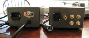
I realize this isn't a large pic, or shows the guts but it's pretty much built exactly like the construction guide says to. No hum at all. Fantastic.
I realize this isn't a large pic, or shows the guts but it's pretty much built exactly like the construction guide says to. No hum at all. Fantastic.
Richard
I bought Phonoclone 3 pcbs from june 2009 which Is for MC
but I got Ortofon VMS 20E catridge which Is MM
Is It possible Phonoclone 3 pcb to be modified to accept MM and How to do It
I bought Phonoclone 3 pcbs from june 2009 which Is for MC
but I got Ortofon VMS 20E catridge which Is MM
Is It possible Phonoclone 3 pcb to be modified to accept MM and How to do It
Richard
I bought Phonoclone 3 pcbs from june 2009 which Is for MC
but I got Ortofon VMS 20E catridge which Is MM
Is It possible Phonoclone 3 pcb to be modified to accept MM and How to do It
Try stripping down to VSPS, sound great:
Project page:
RJM Audio - The Very Simple Phono Stage
My PCB:
Picasa ???? - johnsonlam - Share
Can be done, but it's a bit of a cludge. If you have the parts and unbuilt then I suggest getting the VSPS300 boards and building that instead.
Just wanted to add that I can offer exchanges on current-release boards for a nominal fee ($5). Send me back the Phonoclone 3 and I'll post you a VSPS300 or vice versa.
I just finished up my VSPS, but the sound is very quiet. Can you help me figure out what's up?
Try stripping down to VSPS, sound great:
Project page:
RJM Audio - The Very Simple Phono Stage
My PCB:
Picasa ???? - johnsonlam - Share
thx for your advice will try to do like you
have you choose other than OP27
what type resistors and caps are good for RIAA
I just finished up my VSPS, but the sound is very quiet. Can you help me figure out what's up?
1. Using moving coil cartridge with VSPS.
2. Incorrect resistance values in R1-R5.
3. Zapped op amp.
Turned out I was using a MC cartridge..
However, now I don't get any sound out of the left channel. Is that the op-amp?
However, now I don't get any sound out of the left channel. Is that the op-amp?
That's possible but unlikely. Try another op amp.
Otherwise it's a bad solder joint or loose wire connection somewhere in the signal path.
Otherwise it's a bad solder joint or loose wire connection somewhere in the signal path.
Hi Richards, i justed finished building the VSPS 300- listening with clearaudio virtuoso woods- nice sound.
Just wonder any tips on modding it further?
Thanks in advance.
Just wonder any tips on modding it further?
Thanks in advance.
About the only tweaking on the boards themselves is the output coupling cap, C3. Other places: upgraded power transformers, different diodes, or investing in a nice phono cable. (Mine is from oyaide... not DIY 🙂)
Good morning. Just built the stereo VSPS on a prototyping board using the 47b schematic and am having a bit of a problem. With the IN- connected to GND, I get no sound. If I disconnect it from GND, I get foggy, fuzzy sound. Distortion isn't the surprise. The surprise is that with GND connected, there's zero sound.
I've given the circuit a very quick once-over and wasn't able to find a problem. I've swapped the NE5532P for another (same) chip and still the same problem. I get a steady 12.48V at the power pins, although I haven't checked that with the GND connected. Yet.
Obviously I've screwed up a connection somewhere and will give it a very thorough check, but wanted to see if you might be able to point me in the right direction. I know it's not much to go on, especially without a photo, but thought I'd give it a shot.
Appreciate your time and any thoughts you might have.
@topdog
IN- OUT- COM and GND must be all connected and at the same potential. Are you using a split supply? Just checking the obvious first. The problem with building it on prototyping board is you can get all kinds of connection errors, but from the language of your post I wonder if its something more basic like you haven't connected the power supply common to the circuit ground for example.
@Crabpeople
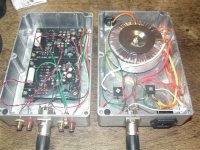
Looks nice, but the wiring is pretty messy. Try cleaning that up so the power wires are well away from the input wires.
Both of you might find the construction guide to be of some help.
IN- OUT- COM and GND must be all connected and at the same potential. Are you using a split supply? Just checking the obvious first. The problem with building it on prototyping board is you can get all kinds of connection errors, but from the language of your post I wonder if its something more basic like you haven't connected the power supply common to the circuit ground for example.
@Crabpeople
Looks nice, but the wiring is pretty messy. Try cleaning that up so the power wires are well away from the input wires.
Both of you might find the construction guide to be of some help.
Thanks for the quick reply. The power supply is from your construction guide. I think you've pointed toward the problem with your comment on the prototyping board. It's a connection error somewhere. Checked voltages more thoroughly and while there's a steady 12v at the op amp, the LM7912 is showing almost zero voltage and is heating up. There's a short somewhere I need to track down.@topdog
IN- OUT- COM and GND must be all connected and at the same potential. Are you using a split supply? Just checking the obvious first. The problem with building it on prototyping board is you can get all kinds of connection errors, but from the language of your post I wonder if its something more basic like you haven't connected the power supply common to the circuit ground for example.
Hi Richard, what Cap do you use for C3?
my transformer -toroidal 100VA rating, i hope this is good enough.
How about the diodes?cause i am using bridge rectifiers as per parts guide.
My phonocable is VDH the first ultimnate-very nice so i am pretty content with it ATM.
Would a pre-regulating power be better?
Thanks.
my transformer -toroidal 100VA rating, i hope this is good enough.
How about the diodes?cause i am using bridge rectifiers as per parts guide.
My phonocable is VDH the first ultimnate-very nice so i am pretty content with it ATM.
Would a pre-regulating power be better?
Thanks.
- Home
- Source & Line
- Analogue Source
- The Phonoclone and VSPS PCB Help Desk