chrismercurio said:I haven't read the whole thread. Has anyone powered this with a battery?
Yes, I have seen several people do it with a battery. However, from what I have read, best results come from higher voltages and also form the toroidal transformer.. Less magnetic interference if I remember from physics.
juluska said:Kevlogg, this toroidal is enough. 5VA is enough, but the bigger you can use will be better. I've used a 50VA. If you are going to do more projects you can use a bigger toroidal to probe another amplifier pcbs.
A very low noise is always present from the toroidal, if you can chose an en capsulated toroidal.
Think in doing it point to point in a protoboard, is more flexible and funny.
Probe with double bridge fast rectifiers and also with schottky discrete double rectifiers. I've probe this and the sound diferent.
cool, thanks for the reply. I will check out those rectifiers. I will also look into a buffer power supply. What I meant to ask is this.... is there a formula I need to know to to equate (match) the rectifier to the transformer. or will any combination work> I am not familiar with (Va- this must be some kind of power measurement?) and rectifier properties.
( I do have a basic understanding of how it manipulates the power supply from AC to a "rippled DC")
I contacted my professor, and he is willing to work out this first project with me, he remembered his first job working as an audio repair technician
at this point, I can't wait to start!
😀 😀
Kevlogg said:This should work, correct?
http://cgi.ebay.com/ws/eBayISAPI.dl...6046&_trksid=p3907.m32&_trkparms=tab=Watching
Its not too surprising to see come around for the third or fourth time. At over 1000 replies, I don't get mad at people anymore for not reading the whole thread...
Don't use a battery. Use the biggest, best transformer you can afford.
Realistically, though, a 25VA or 35VA toroid with 2x12VAC will do the trick nicely. That one on ebay, or something similar from Digikey or wherever. It should be about $20, less if surplus.
Diodes: use a bridge rectifer, or two, bigger current is better, but anything above 1A and 100V is fine.
And don't forget the fuse.
Dumb non-EE ?,
What is the formula for voltage after bridge rectification? (please use the VSPS as the example)
Thank you,
Chris
What is the formula for voltage after bridge rectification? (please use the VSPS as the example)
Thank you,
Chris
chrismercurio said:Dumb non-EE ?,
What is the formula for voltage after bridge rectification? (please use the VSPS as the example)
Thank you,
Chris
secondary AC voltage x (times) 1.4 will get you the DC voltage assuming you have filter caps.
12VAC x 1.4 = 16.8VDC
2 X 0,7 is the voltage drop if you have a full wave rectifier bridge, if you have only one diode it will be only 0,70, and if you have schottky diodes it will be about 2 x 0,30 or 0,30
You are absolutely correct, but if a person doesn't know how to calculate AC to DC voltage I wasn't going to throw diode voltage drops, wire/trace resistance and cap ESR at him.
But you are 100% correct...
But you are 100% correct...
hello how much gain in db is the Phono clone when i use this cart ?:
coil imp 22 ohm
load imp 100 ohm
load cap 150 pf
output voltage 0,5 mv
i hope you can help me with this
coil imp 22 ohm
load imp 100 ohm
load cap 150 pf
output voltage 0,5 mv
i hope you can help me with this
That first circuit analysis class was quite a few years ago...and never put into practice.
thanks guys.
Chris
thanks guys.
Chris
12 VAC secondaries gets you about 17 V DC, 16 V if you use a bridge rectifier on both windings.
The simplest (VAC x 1.41) formula works quite well here, because the diode drop and ripple is compensated by the load regulation of the transformer. i.e. you lose about a volt to the diodes, but gain about a volt because the transformer is only lightly loaded.
/R
The simplest (VAC x 1.41) formula works quite well here, because the diode drop and ripple is compensated by the load regulation of the transformer. i.e. you lose about a volt to the diodes, but gain about a volt because the transformer is only lightly loaded.
/R
thanks AHAJA
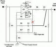
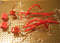
Following your advices i changed the rectifier bridge for two schokky diodes rectifiers with parallel capacitors and added one 47uf and 100nf caps next to the opamp +v and -v. I am impressed how well it sounds now. Now i'm going to change the riaa network with your modifications. Can you explain with plain words hows this modifications can improve the sound?
ahaja said:Hola.
These tricks much improve the sound.
VSPS and also Phonoclone.
ahaja said:...and:
Following your advices i changed the rectifier bridge for two schokky diodes rectifiers with parallel capacitors and added one 47uf and 100nf caps next to the opamp +v and -v. I am impressed how well it sounds now. Now i'm going to change the riaa network with your modifications. Can you explain with plain words hows this modifications can improve the sound?
Attachments
🙂 I know that it works.
Thorsten wrote about it here: http://www.diyaudio.com/forums/showthread.php?postid=388315#post388315
Curently I'm working on these projects (pcb) on our polish audio forum, and it looks: http://www.audiostereo.pl/forum_wpisy.html?temat=48037&p=1#k
Two layer pcb.
Another mod is place on the top of opamp beetwen power legs cap 220-470nF. Wima MKS4 (raster/pcm=10mm).
Regards Krzysztof
ahaja said:🙂 I know that it works.
Thorsten wrote about it here: http://www.diyaudio.com/forums/showthread.php?postid=388315#post388315
Curently I'm working on these projects (pcb) on our polish audio forum, and it looks: http://www.audiostereo.pl/forum_wpisy.html?temat=48037&p=1#k
Two layer pcb.
Another mod is place on the top of opamp beetwen power legs cap 220-470nF. Wima MKS4 (raster/pcm=10mm).
Regards Krzysztof
Excuse my little knowledge in electronics. I guess the modified schedule for beginners is this:
Am I right?
Attachments
ahaja said:Hello
Rather you're wrong.
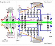
I think you should do that way (if you made your pcb and connections based on layout from Richard's site !).
K
Soldering in this very moment. I think this night i could listen it.
Thanks
ahaja said:Hello
Rather you're wrong.
I think you should do that way (if you made your pcb and connections based on layout from Richard's site !).
K
DONE
At first glance very good results, more detailed LF.
My reference lps:
Something Else, Cannonbale Adderley
Tom Waits, Asylum days
Ella Fitzgerald & Louis Armstrong compilation
Dire Straits, Love over Gold
Thank you very much Ahaja, BRAVO!!!!!!
Attachments
- Home
- Source & Line
- Analogue Source
- The Phonoclone and VSPS PCB Help Desk