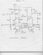
I started building the Pearl phono stage and decided to go with a balanced output stage. Because of all the information that now exists on the forum for the X topology I thought I might try one in this application. My goal was to improve the perfomance of the pearl output stage but still stay close to the original design and keep it as simple as possible. The resistor values for the cross-coupling are a guess taken from the P1.7 preamp. All of Nelsons comments regarding unbalanced operation of the X topology I hopefully have implemented correctly! As far as the feedback is concerned I have no clue at this point. It may not have enough excess gain to give any away in my particular application. I left the source resistor out so the J-FETs run at IDss, about 10-12ma.
I hope Nelson and the rest of you will please comment on the attached schematic. This is my first attempt at audio design in recent history so try not to be too tough on me.
I hope Nelson and the rest of you will please comment on the attached schematic. This is my first attempt at audio design in recent history so try not to be too tough on me.
Attachments
I would drop the 3.9K's to ground for this
application, which is single-ended input.
Probably you will end up with the pot at 0 ohms,
but that's OK.
Oh yeah, and add some output series resistance for
HF stability, 100 to 220 ohms.
application, which is single-ended input.
Probably you will end up with the pot at 0 ohms,
but that's OK.
Oh yeah, and add some output series resistance for
HF stability, 100 to 220 ohms.
I've always wondered why more phono stages aren't balanced INPUT, seeing as a cartridge is an inherently balanced device. Dealing with such low voltage signals, I'd think that a balanced input would reduce noise. I built a phono stage based on the INA103 instrumentation amp, which is balanced input. It's very quite, especially once I had the phono cable sheild properly grounded 😀
How could we convert this Pearl-X, or the original Pearl, or even the Ono to balanced input? I don't care so much about balanced output, the signal is pretty robust at that point.
RonS
How could we convert this Pearl-X, or the original Pearl, or even the Ono to balanced input? I don't care so much about balanced output, the signal is pretty robust at that point.
RonS
Design advice
5K and 10K votage divider should be changed to 15K and 10K.
500 ohms too small for collector resistor, Very low open loop gain.
What is the closed loop gain that you want? Do not design until you know.
DO NOT RUN JFETS AT Idss. 3 to 5 mA in each Jfet is probaly enough if this circuit is to drive >= 50K loads.
SK170s should be biased less than Idss each half of SK389.
Gate resistors on SK389.
You need a negative voltage supply also.
Balanced Phono Input
Well, I'm sure you are correct, but how do the studio guys do it with mic's? Essentially they are the same, a low level balanced signal, going into either an active balanced stage like the INA103, or a transformer. I understand that the CMRR degrades for an active stage if the source impedance isn't equal in both legs, but it should still be worth something, no? Good transformers, like the Jensen's, are expensive.
Any thoughts?
RonS
With a moving magnet cartridge, the signal is high
enough, but the load impedance is also high, so you
get a lot of common mode pickup.
With a moving coil, the impedance is low, but so is the
output, so the signal to noise range is lower.
Your typical microphone is high output but low impedance,
so it is easier to make work with active balanced input.
Balanced MC stage
Yes, that's exactly what I'm refering too, low signal level from MC cartridge. Is there nothing that can be done to improve the CMRR in a phono stage? Or is it a moot point?
RonS
With a moving coil, the impedance is low, but so is the
output, so the signal to noise range is lower.
Yes, that's exactly what I'm refering too, low signal level from MC cartridge. Is there nothing that can be done to improve the CMRR in a phono stage? Or is it a moot point?
RonS
Nelson and Harry thanks for the help. I'll be driving a 22K balanced load (P1.7 Input) with the phono section in the same box. I'd like to obtain a gain of about 24dB-30dB out of this circuit.
As far as power supplies go I'd like to stick with a single supply to make this mod as painless as possible since the basis is the Pass labs Pearl PCB.
As soon as I get further along I will post an updated schematic.
As far as power supplies go I'd like to stick with a single supply to make this mod as painless as possible since the basis is the Pass labs Pearl PCB.
As soon as I get further along I will post an updated schematic.
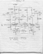
The Pearl-X Revision 1
This version incorporates Nelson's and Harry's comments implemented correctly I Hope! The changes are:
1. Deleted 3.9k's dangling to ground(Nelson is this correct)
2. Added 200 ohms at the outputs and gates of diiff pair (HF
stability)
3. Rebiased to less than Idss (10ma) and added another dual J-
FET to the Diff pair (more gain)
4. Increased collector resistor on cascodes(more gain)
5. Added feedback, gain is about 21X I think, which is enough for the second stage since my High output MC puts out about 3mv.
Thanks again and any additional comments are greatly appreciated.
Vince
Attachments
The Pearl-X Revision 1
I think the following might be helpful.
http://www.borbelyaudio.com/ae599bor.pdf
http://www.borbelyaudio.com/ae599bor.pdf
http://www.schuro.de/Daten/Japanhalbleiter/2SK170.pdf
http://www.schuro.de/Daten/Japanhalbleiter/2SK389.pdf
The circuit needs a negative supply for DC coupled inputs.
The open loop gain is much lower than you think.
Design for Green bias group is recommend since those are easiest
to buy.
Use matched diff pair for both halfs of circuit (one SK389 for both output phases or you lose any advatage in using a matched pair device and might as well use 2SK170s for all fets.)
Check out simlation program:
http://www.diyaudio.com/forums/showthread.php?threadid=4735
Models:
http://www.diyaudio.com/forums/showthread.php?threadid=4797
Keep plugging. you are asking good questions on a circuit block that is very likely of interest to many others. Feel free to ask further question after reading the above links; which will give you
more answers than I can.......
H.H.
Harry
Great info and thanks for your advice. I'll eventually get the hang of this. The itterations are the result of my thought processes ( thinking out loud). I've been sitting back absorbing the info on this forum and eventually hope to be able to contribute.
Vince
Great info and thanks for your advice. I'll eventually get the hang of this. The itterations are the result of my thought processes ( thinking out loud). I've been sitting back absorbing the info on this forum and eventually hope to be able to contribute.
Vince
My suggestion is somewhat different
I am completing design of a 2 stage DC coupled balanced Pearl. No X, though -- probably not worth it in this application if you ask me.
I use 16 n-channel JFET's for the input in a long tailed pair (pair of 8) driven by a current source. Degeneration on each source. I also use cascoding to shield the devices from Miller effect. Very similar to a doubled up stock Pearl input if you know what I mean.
The second stage is identical except it is p-channel, and by careful choice of components and voltages brings the signal DC back to where it came from -- let us call that zero ... This stage is also very similar to a stock Pearl stage 2.
I am gunning for 70-80dB gain at 1KHz after passive EQ. I am also re-evaluating whether I want to use passive RIAA, combined RIAA or active RIAA. I had originally planned to do the RIAA across phases instead of to ground. I still hold this as the main gain plan, but I need to figure out a way to cut gain at DC, and I was really gunning for no coupling caps. Hmmmm. I could do a combined or active RIAA and cross between left input and right output (and vice versa) in order to get the required negative gain, or do the gain stuff across each gain stage which should be quite possible. At this juncture though phase to phase with some LF rolloff generated somehow looks like the winner.
Petter
- Status
- Not open for further replies.
- Home
- Amplifiers
- Pass Labs
- The Pearl-X