just connect it to siggene and crank it until movement
triangle wave best , rectangle after , but even with sine it'll work
replace tantal cap(s) just in case - with solid or proper elco
I can make the pointer to move up to around 7 (it starts at 6k rpm) with kilohertz signals. At 166 Hz (10 000 rpm) it just barely moves. I have tried some 8 to 12 vpp and it seems to react more to which wavetype sq/tr,st etc.
I wonder what it counts and how. What affects the coil so the pointer moves up?
aha - (just) two end connection ........ one end connected to 12V , other end connected to switched gnd
btw. simplest test is if you have a car around ..... preferably with older (so, points ) circ
or just connect it to one dragsta coil
btw. simplest test is if you have a car around ..... preferably with older (so, points ) circ
or just connect it to one dragsta coil
Well we wired it up in the garage and made some throttlemoves but nothing happened, so we assumed it might either be broken or wrongly wired. But since it starts at 6 k maybe we didnt rev it enough. No mufflers in a villa garage exactly dont call for crazy rev gazzing. So I braught it home to look at it.
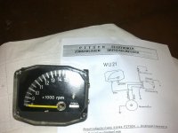
On the picture and in the previous text one can figure out that pin 1 shall be connected to the breaker. A breaker has constant 12 VDC from battery via primary ignition coil that collapses when the breaker looses contact with ground which causes the HV spike on the secondary coil to ignite the plug.
To me this must mean that the Kröber somehow is fed with something like a 80-90 % +12 VDC and 10-20 % 0 VDC in a rectangle wave? It looks like it have a circuit that starts with a 68 ohm resistor, then a rect diode, maybe for polarity protection, then I see one leg to a BCY58 etc. Maybe I have to rip it out...
Id like to try to create that signal in my gen, have to read the manual. Gotta offset the signal so it dont go to minus but start at 0 and goes to +12 V.
Last edited:
No I just dug up my old nonprogrammable gen that was easyer to tune in to the right freq-span and voltage. Will report figures tomorrow, putting the gamer animal to bed
As the days go by I feel myself more and more miserable.
On the other hand, you'd not feel better if the days didn't go by
No I just dug up my old nonprogrammable gen that was easyer to tune in to the right freq-span and voltage. Will report figures tomorrow, putting the gamer animal to bed
Strange. It seems to show about 1 rev per 2 turns. I guess, since I have 2 breakers and coils take the signal from both and tie them to one with rectifier diodes. Whatyathink?
if ya look at first parts in thingie itself , there already must be diode and probably series resistor
if yes , just duplicate that , to have one per breaker circ
didn't checked - is phase on CB750 180deg between two breakers ?
if yes , just duplicate that , to have one per breaker circ
didn't checked - is phase on CB750 180deg between two breakers ?

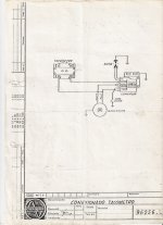
Heres some simplified schemas over regular 2 coil ignition. One coil fires cyl 1 and 4 and the other fires 2 and 3. They fire both at compression and exhaust cycle.
I guess I was wrong before stating that the signal is 80% 12 V and 20% 0V in squarewave. It would be 12 V during breaker open short period and 0 V at breaker closed long period.
Since they open 180 degrees off phase to eachother I would get twice the amount of 12 V signals as when taken from only one breaker, wouldnt you say? Then I have to reverse block them with diodes otherwise they will fire for eachother.
Could that be a plan?
Attachments

yup. but put some R in series with diodes , to suppress spikes
start high (100K , 47K ? ) , go lower until you get needle move
start high (100K , 47K ? ) , go lower until you get needle move
One of the things that stole my time so much from diy'ing audio. (I have an itch to dig into audio again 🙂 )
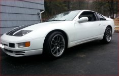
It was a badly neglected '90 300zx. The entire job was DIY except the windshield install and welding of the cast ally oil pan. There was no 'Kit' involved. It has a self built GM 5.3L with high compression and corvette camshaft. Using stock Nissan 5-sp gearbox with custom flywheel and clutch parts from .. Isuzu 🙄
Engine is managed with microsquirt. Suspension is simple Tein springs w/ KYBs. All the gauges work like factory and you can hop in, turn the key and go with no trouble.
Has some tunes too...
Not a big dollar build - mostly enormous labor and scraps... but I'm proud of the result.
Attachments


Last edited:
- Home
- Amplifiers
- Pass Labs
- The Pass Pub: The High-End Off Topic Thread