I pulled the d6, d2, r1, r2 and also the q2. trying to find if any of them were the problem. well that didnt help much..
Ill do what you suggested now.
Ill do what you suggested now.
I pulled the d6, d2, r1, r2 and also the q2. trying to find if any of them were the problem. well that didnt help much..
Ill do what you suggested now.
Yep, just follow those traces you can see on the bottom of the board going to pin 7. Either one of those 4 things hooking to it has to be shorted, or a short (solder bridge) directly to that trace.
Yep, just follow those traces you can see on the bottom of the board going to pin 7. Either one of those 4 things hooking to it has to be shorted, or a short (solder bridge) directly to that trace.
I made a very noob mistake. r25 was 133ohms.
put the correct value in and now there is no more short. Ill solder everythg and see what happens.
thanks for the help agdr
I made a very noob mistake. r25 was 133ohms
Yes but you've successfully troubleshooted it! 🙂 Mistakes like that are easy to do and can be hard to find. You should have music shooting out of that O2 real soon.
Last edited:
Hi guys,
been reading part of this big thread, but was wondering where to get the PCB and shematic.
Thanks
Tony
O2 Details is the best place to start. He has the Schematic, board layout, etc.. Check the Vendor bazaar here for any Boards for sale (a few people are offering completed boards, but they may sell you one unpopulated).
O2 Details is the best place to start. He has the Schematic, board layout, etc.. Check the Vendor bazaar here for any Boards for sale (a few people are offering completed boards, but they may sell you one unpopulated).
Thanks Slim
Alright. I think I may be getting close.
Volume control is working properly (I ran a wire to the 20mm pot holes after damaging the board cups when trying to remove the pot -- it seems to work.)
After resoldering the leads near the U2 chip, I now have these measurements.
AC, on, no batteries for U2
1=-11.7
2=-8.8
3=-10
4=-11.7
5=-10
6=-11.7
7=8.5
Are these within proper ranges?
Measuring the resisters on top of the board (still connected), I have the measurements
R25= .39 on 20M
R5= .23 on 20M
R9= .02 on 20M
Alright. I think I may be getting close.
Good job! Those voltage readings look a lot better. P2 of U2 is spot on now. You didn't list the positive rail voltage at P8, but that has to be OK (around +11.8Vdc) to produce that correct P2 reading. You must have your U2 back in the socket too since those output readings on P1 and P7 are doing their thing (almost) properly. The voltage on P7 is a little lower than what I would expect, but that could just be due to part tolerances.
What is the color code on your R25? The fellow I helped a few posts up had a wrong value in there. Maybe there are a couple of color codes that look pretty similar. If R25 is too low it could drag P7 down. Your R25 measurement is probably correct though. You are essentially getting R9 plus some power supply internal resistance, which is essentially in parallel across R25.
OK, so you've fixed up the U2 circuit and it is should be sending the proper control signals to the mosfets. So back to the original test you did in your first post in #1834 of running it on batteries with the chips in (headphones still unplugged though!), rather than AC, and then pulling out one battery and seeing if P4 and P8 of U4 go below one volt. P4 and P8 on U4 should be around the rail voltages (-11.8Vdc and +11.8Vdc) before pulling the battery out. If they do drop the mosfets have toggled properly and your power management circuit is working.
If that test works your O2 may be working. Run through RocketScientist's list of setup instructions again - especially the one about measuring the DC output voltage offset of each output channel and confirming it is around 3mV and not higher - and you may have a working O2. Give it a try after confirming those tests.
If one channel still won't work with the pot, try reheating both ends of R16 and R22, even if they look OK. Also make sure you have done that gain switch mod of bending the tab on the front left corner of the gain switch under, so as not to hit that via hole under it.
Last edited:
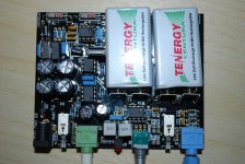
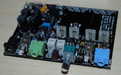
O2/DAC combo
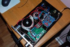
Thought I would share this.
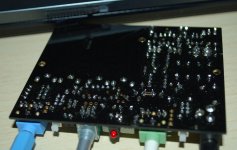
An O2 and AK4393(with a couple of mods) crammed into a rather nice chinese aluminum enclosure. Need to straighten up the wiring.
Many thanks to RS for a very nice amp.
The input to the DAC is via an HA info spdif device.
This is my first effort at going PC based music system.
I'm very happy with the sound but would consider replacing the DAC with a decent USB input board. Anyone suggest one that would fit and sound as good?
Cheers
Peter
Thought I would share this.
An O2 and AK4393(with a couple of mods) crammed into a rather nice chinese aluminum enclosure. Need to straighten up the wiring.
Many thanks to RS for a very nice amp.
The input to the DAC is via an HA info spdif device.
This is my first effort at going PC based music system.
I'm very happy with the sound but would consider replacing the DAC with a decent USB input board. Anyone suggest one that would fit and sound as good?
Cheers
Peter
Attachments
O2/DAC combo
Thought I would share this.
An O2 and AK4393(with a couple of mods) crammed into a rather nice chinese aluminum enclosure. Need to straighten up the wiring.
Many thanks to RS for a very nice amp.
The input to the DAC is via an HA info spdif device.
This is my first effort at going PC based music system.
I'm very happy with the sound but would consider replacing the DAC with a decent USB input board. Anyone suggest one that would fit and sound as good?
Cheers
Peter
O2 Case - in LEGO!
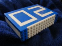
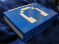
Here's the result of a quick experiment to see if it was possible to make an O2 case in Lego. The end result is quite robust, and I'm pleased with how it looks. I haven't yet tried fitting the electronics, it will need to be glued togther first, and probably a little internal machining to clear the taller components. Anyhow, here's a couple of views of it so far. DSCF1296.jpg DSCF1298.jpg
Here's the result of a quick experiment to see if it was possible to make an O2 case in Lego. The end result is quite robust, and I'm pleased with how it looks. I haven't yet tried fitting the electronics, it will need to be glued togther first, and probably a little internal machining to clear the taller components. Anyhow, here's a couple of views of it so far. DSCF1296.jpg DSCF1298.jpg
Attachments
Here's the result of a quick experiment to see if it was possible to make an O2 case in Lego. The end result is quite robust, and I'm pleased with how it looks. I haven't yet tried fitting the electronics, it will need to be glued togther first, and probably a little internal machining to clear the taller components. Anyhow, here's a couple of views of it so far. DSCF1296.jpg DSCF1298.jpg
that is a great idea! 😉 did you consider using tiles for the front to hide the studs?
Stefan
did you consider using tiles for the front to hide the studs?
I think I'll probably just mill the front flat to take the studs off, I don't have any Lego pieces that are just flat plates with no studs.
If you mill the studs off you might end up with little holes in the front from the mold, If you do not have the plates I could send you some, if I counted correctly the case is 4 x 16 studs? PM me your address and I send you 8 white 1x8 tiles for it 😉
And let the LEGO-dealing commence ^^
I actually like the idea.
But mine will be hard and strong, machined stainless steel. A man-case, so to say 🙂
I actually like the idea.
But mine will be hard and strong, machined stainless steel. A man-case, so to say 🙂
Exactly.
Sometimes music is best served just like love: dirty and intense.
Best regards,
Jokener
P.S.: Love does not require you to fight with a CAM-application to mill it in only two steps!
Well, at least not in my world.
Sometimes music is best served just like love: dirty and intense.
Best regards,
Jokener
P.S.: Love does not require you to fight with a CAM-application to mill it in only two steps!
Well, at least not in my world.
For anyone interested on upgrading their plastic knob on their O2 here a LINK
They are not that BIG!!!
An externally hosted image should be here but it was not working when we last tested it.
An externally hosted image should be here but it was not working when we last tested it.
They are not that BIG!!!
Last edited:
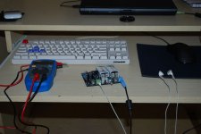
This was really nice first soldering job 🙂 Only thing I had problems with was I soldered all three legs of U6 together 🙁 I needed like half an hour to actually correct that mistake. Oh yeah and I didn't have any good clips so it looks a bit messy.
After some testing with old earbuds it seems to work well. Now before I put it in alu case. Just need to find some alcohol and clean the board because its dirty after all that soldering.
Some photos 🙂
After some testing with old earbuds it seems to work well. Now before I put it in alu case. Just need to find some alcohol and clean the board because its dirty after all that soldering.
Some photos 🙂
Attachments
%20Amplifier&txt=%3Cimg%20alt%3D%22Alu_Knob.JPG%22%20height%3D%22262%22%20src%3D%22http%3A%2F%2Fcdn.head-fi.org%2F8%2F87%2F350x262px-LL-87487348_Alu_Knob.jpeg%22%20width%3D%22350%22%3E&jsonp=vglnk_jsonp_13286525997461)
Hello,
I just received a built o2 from a member who put it together for me. When the o2 is being turned off, there is a deafening pop through my headphones..... The member said this is normal, but I would like to confirn that information please. Does this happen to everyone ?
Thanks
Darren C
dgcrane
I just received a built o2 from a member who put it together for me. When the o2 is being turned off, there is a deafening pop through my headphones..... The member said this is normal, but I would like to confirn that information please. Does this happen to everyone ?
Thanks
Darren C
dgcrane
- Home
- Amplifiers
- Headphone Systems
- The Objective2 (O2) Headphone Amp DIY Project