Wow, it worked, well almost....
I linked pin 4 from U2 to pin 4 on U4 and the amp has life, It 'sounds' perfect yet the power LED (D7) is still not lit. Looking at the circuit do you think that Q2 being faulty would also also cause the LED to not work?
I linked pin 4 from U2 to pin 4 on U4 and the amp has life, It 'sounds' perfect yet the power LED (D7) is still not lit. Looking at the circuit do you think that Q2 being faulty would also also cause the LED to not work?
Wow, it worked, well almost....
I linked pin 4 from U2 to pin 4 on U4 and the amp has life, It 'sounds' perfect yet the power LED (D7) is still not lit. Looking at the circuit do you think that Q2 being faulty would also also cause the LED to not work?
I just did what was said here (linked pin 4 from u2 to u4) and i now have beautiful sound, but in doing so it shorted out the led.. after that i took the jumper wires off u2 and u4 and still had sound but the led was still off.. ok so with the led connected but not lite im geting +8.3v at C21, 11.7v at pin 4 on u2,u4 and so on.. but when the led is taken away C21 is -11.7 and there is no power at u4... 😕
I just did what was said here (linked pin 4 from u2 to u4) and i now have beautiful sound, but in doing so it shorted out the led.. after that i took the jumper wires off u2 and u4 and still had sound but the led was still off.. ok so with the led connected but not lite im geting +8.3v at C21, 11.7v at pin 4 on u2,u4 and so on.. but when the led is taken away C21 is -11.7 and there is no power at u4... 😕
You have to fix the LED. In the O2 the voltage across the LED is also used as the voltage reference for the comparator in the U2 power management circuit. If the LED isn't on the comparator will never switch and the two mosfets won't come on. The LEDs have been known to fail on their own. The LED is just in series with one resistor and placed across the +12V and -12V power rail. You haven't said if you have the -12Vdc on D5 along with the +12Vdc you measured. If you do, and your LED isn't on, your LED is dead. Replace that and then post your voltage readings on all the pins of U2 if it still isn't working, to track down why the power management circuit isn't turning on the negative rail mosfet.
If you have to order the LED from Mouser you should order another U2 comparator chip and both mosfets at the same time, since they are cheap and one or more could wind up being involved. It also couldn't hurt to order two more NJ4556A chips since they are also cheap, and only having one power rail has also been known to kill NJM4556A's. Even if the output chps are working now they might not be before you get it fixed.
The LED in the O2 also HAS to be red. The other colors of LEDs have different forward voltage drops that will confuse the comparator circuit.
Last edited:
Wow, it worked, well almost....
I linked pin 4 from U2 to pin 4 on U4 and the amp has life, It 'sounds' perfect yet the power LED (D7) is still not lit. Looking at the circuit do you think that Q2 being faulty would also also cause the LED to not work?
So the amp itself appears to be OK. That's good. The LED is "across" the power supply with a series resistor R6 to limit current. If the LED has failed then its probably because of some momentary short that occurred as you were working on it. Its easily done.
Is U2 in a socket ? If it is, then just pull it out and then see if the LED lights. If it does then the LED is OK and U2 has an internal short. If it doesn't then it would appear the LED is faulty.
The LED type is "critical" only in that its used as a stable voltage reference for determining the low battery cut off point (and also that its a high efficiency type so that its bright on the limited current R6 can provide)
Lets see what the problem is first...
OK I checked with U2 out of its socket the LED is still off.
Measuring across the LED there is continuity
(can LED's create a short when they blow?)
So to recap...
From ground to one end of the LED is +11.7v
From ground to the OTHER end of the LED is still +11.7v
Measuring from ground to one end of R6 is +11.7v
Measusing from ground to the OTHER end of R6 is -11.7v.
I get these same readings with OR without U2 in its socket.
(all these tests were done WITHOUT the U2 pin 4 link wire by the way).
Last edited:
Sounds like the LED is short, which is a typical failure mode if its been zapped by excess current 🙂 If you measure the LED on ohms range (amp off) it probably reads very low if not short.
So you need an LED and a new FET up to now. I'd be surprised if the comparator is zapped tbh. Slim chance that the comparator has an internal short and that has zapped the LED in which case a new one would blow too... very doubtful thats happened though.
So you need an LED and a new FET up to now. I'd be surprised if the comparator is zapped tbh. Slim chance that the comparator has an internal short and that has zapped the LED in which case a new one would blow too... very doubtful thats happened though.
Scrub that... not thinking straight on this... but yes, the LED appears duff.
If you now remove the shorting link we added connecting the pin 4's together and remove the comparator does the amp come on and work ?
If you now remove the shorting link we added connecting the pin 4's together and remove the comparator does the amp come on and work ?
Scrub that... not thinking straight on this... but yes, the LED appears duff.
If you now remove the shorting link we added connecting the pin 4's together and remove the comparator does the amp come on and work ?
My previous readings posted stated that I had the same with or without U2 in its socket but I found a couple of discrepancies :
I get the following readings WITH U2 in its socket.
Ground to one end of the LED is -11v
Ground to the OTHER end of the LED is still -11v
Ground to one end of R6 is -11v
Ground to the OTHER end of R6 is +11v
Ground to one end of C21 is -11v
Ground to the OTHER end of C21 is still -11v
Ground to one end of R8 is -11v
Ground to the other end of R8 is +11v
I get the following readings/differences WITHOUT U2 in its socket.
Ground to one end of C21 is -11v
Ground to the OTHER end of C21 +8.4v
Ground to one end of R8 is +8.4v
Ground to the other end of R8 is +11v
Sorry if you were reading this while I was editing it, I had to go back over and make sure my figures were correct.
EDIT: Removal of comparator= Amp still not working.
Last edited:
Give me a minute while I go to another PC because I haven't got the circuit on this one and IE9 (Vista) won't open the google docs.
The LED seems faulty. Two definite tests on that.
1. If the LED reads short circuit on the meter (ohms range) with U2 removed its definitely duff.
2. The voltage across a good RED LED should be around 1.9 to 2.2 ish volts. If you have not got that with U2 removed then its duff.
Your voltage readings do point to the LED being faulty.
We need to test the FET. I've just printed the circuit so its easier to work on.
Can you measure the following.
1. Voltage on pin 1 of U2 with respect to ground.
2. Voltage on pin 7 of U2 with respect to ground.
3. Voltage across C16
4. Voltage across C21
Do you have any spare /components to work with such as old LED's and resistors etc ?
1. Voltage on pin 1 of U2 with respect to ground.
2. Voltage on pin 7 of U2 with respect to ground.
3. Voltage across C16
4. Voltage across C21
Do you have any spare /components to work with such as old LED's and resistors etc ?
I get 9.5 ohms resistance over the LED with no power to the amp and U2 removed.
Should I desolder the LED and check the voltages at that point?
Should I desolder the LED and check the voltages at that point?
That's low enough to prove its duff. We'll leave it in place for now because it will actually help with the other tests.
Ultimately replacing the LED, U2 and the FET has to fix this but its nice to diagnose exactly what is wrong.
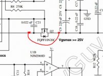
Does pin 7 of the comparator really go direct to the FET Q2 gate or is there a series resistor added (like R24 that drives Q1) ?
Ultimately replacing the LED, U2 and the FET has to fix this but its nice to diagnose exactly what is wrong.
Does pin 7 of the comparator really go direct to the FET Q2 gate or is there a series resistor added (like R24 that drives Q1) ?
1. Voltage on pin 1 of U2 with respect to ground. = -11v
2. Voltage on pin 7 of U2 with respect to ground. = -11v
3. Voltage across C16 = 22.8v
4. Voltage across C21 = 0v (between ground and each end I get both -11v)
I do have 'some' resistors but not much at all, I have some working LED's though.
2. Voltage on pin 7 of U2 with respect to ground. = -11v
3. Voltage across C16 = 22.8v
4. Voltage across C21 = 0v (between ground and each end I get both -11v)
I do have 'some' resistors but not much at all, I have some working LED's though.
Pin 7 voltage is the problem. That should be "high" at plus 11. Pin 1 and 7 mirror each other. When the comparator detects low battery voltage pins 1 and 7 will change state and turn the FET's off.
OK... lets prove in one go whether the FET's and or comparator are duff. Make sure you know which FET is which, Q1 and Q2 and then remove both.
If you then test the amp you should find pin 7 has gone high to plus 11 volts. If it has the comparator seems OK. If it hasn't then the comparator is duff.
OK... lets prove in one go whether the FET's and or comparator are duff. Make sure you know which FET is which, Q1 and Q2 and then remove both.
If you then test the amp you should find pin 7 has gone high to plus 11 volts. If it has the comparator seems OK. If it hasn't then the comparator is duff.
Pin 7 of the comparator definitely goes direct to Q2 gate, I just checked and there is zero ohms resistance between those points.
Pin 7 of the comparator definitely goes direct to Q2 gate, I just checked and there is zero ohms resistance between those points.
OK, that's the way its designed so no problem, just a little unusual. Doesn't change anything.
OK so I am to desolder Q2 and Q1 at the same time then measure between ground and pin 7 on U2, or just remove Q2 then measure before removing Q1?
What puzzles me is that its hard to believe that the FET could be faulty as its such a highly rated part and FET's are extremely robust normally, however.......
Another quick thought. Does pin 4 and pin 7 of U2 read short or very low resistance when measured between them ?
Another quick thought. Does pin 4 and pin 7 of U2 read short or very low resistance when measured between them ?
- Home
- Amplifiers
- Headphone Systems
- The Objective2 (O2) Headphone Amp DIY Project