I've built one o2 and love it, I've got a PCB and enough components to build another but want to configure it for preamp duties instead, has anyone got any tips on converting an o2 for preamp duties? I'd imagine it's just resistor changes but not sure where to start?
I would think you would want to keep the gain to the lower end of things. Perhaps configure it for 0 gain on one setting an 2-4x on the other. Unless you have very low output sources, that should do it.
From NavGuys' blog:
THE GAIN RESISTORS: Before you solder in the four gain resistors by the gain switch, you might want to consider different gains than the approximately 2.5X and 6.5X default values. You want just enough gain so typical music plays loudly enough with your headphones and source and not much more. Extra gain means using less of the volume control’s range, more noise, more distortion, and makes accidental headphone damage more likely. Here’s what you need to know about calculating gain:
Lower Is Safer - Lower gain settings make the amp less likely to damage headphones by limiting the maximum output voltage to only approximately what’s needed.
Lower is Cleaner – As shown in the first article, there’s a slight increase in distortion, especially at high frequencies at higher gain settings. Lower gains also result in lower noise.
Resistor Values – The O2’s gain (for one channel) is:
Low Gain Ratio = 1 + R16/R17
High Gain Ratio = 1 + R16/R19
Voltage Gain in dB = 20 * Log(Gain Ratio)
Example – The standard amp has R16=1500 and R17= 1K so 1 + 1500/1000 = 2.5X. And 20*Log(2.5) = ~ 8 dB.
Feedback Impedance – For many reasons it’s generally best to leave R16 and R22 at 1500 ohms unless U1 is replaced with a weak op amp that can’t handle a 1.5K load.
See The BOM - Gain resistors are pre-calculated in the BOM parts list for gains of 2X – 12X. For 1X gain just leave out the gain resistors (or clip one end if they’re already installed).
For my requirement it's not necessary, the source is a Raspberry Pi, playing audio via MPD through a USB DAC, audio level is controlled by MPD.
Hi all! I want to make a custom o2 that is as small as possible (only using batteies) so i want to ask if the filter section for batteries is really need or can i omit it? Like in the Grado Ra1, there are no filter capacitors too.

A while back I got to thinking about modifying the o2 into a phono preamp. Today I decided to grab my turntable and hook it up to the inputs of my o2 to see what happens. The cartridge is a stanton 500 mm and I had to put the o2 on the high gain setting to get some output. What I ended up with was enough output to listen to on headphones with the volume almost maxed out. I did this as a sort of a proof of concept to see if this was an avenue worth pursuing. If I want to continue by adding an RIAA filter, where would the best place to do that be? Would I want to replace r16 and c19 with something like this? Would I want to find someway to replace c13 with an riaa filter? Or is there another way to go about this?
The O2 is not configured for the amount of gain you need in a phonostage. Trying to adapt it would be extremely difficult and likely more expensive than just building a good phonostage by itself. Look at the RJM VSPS RJM Audio - The Very Simple Phono Stage
Or the Hagerman Bugle 2 (This one looks fantastic...) Hagerman Technology LLC: Bugle2 Phonostage
Or the Hagerman Bugle 2 (This one looks fantastic...) Hagerman Technology LLC: Bugle2 Phonostage
6l6 I know that the gain is not set for phonostage duty when stock but NwAvGuy made it pretty simple to modify the gain of the amplifier. The o2 makes a great headphone amplifier and a pretty decent preamp. Dont you think it would do a decent job modified to be a phono preamp? Aside from changing the gain and the possible noise associated with higher gain, are there other problems I have not considered?
I have been looking at the VSPS 300 and tetra as kits but I thought it might be fun to try something new.
I have been looking at the VSPS 300 and tetra as kits but I thought it might be fun to try something new.
Phonostages need MUCH more gain than you think... With passive RIAA you will need about 40db in the input stage as the phono EQ is very lossy and will eat most (or all) of that gain. You will then need to have another 40db (or more) db gain in the second stage to give you a signal big enough to do something with.
This is really a place for a dedicated circuit... The O2 is such a nice (and very useful) piece of gear that it's worth having around as-is.
The VSPS is cool, as is the Tetra. You couldn't go wrong with either. However, I will say it again, the Hagerman looks to be awesome. (I'm looking at making an opamp-based phono, and the Bugle2 has a ton of neat things in it...)
not a chance DJNUBZ, not only will the gain and way to much noise be a problem. the very low, but not zero, source impedance (and inductance) presented by phono cartridges, makes it an even worse proposition. is your Cart MM or MC? i'm guessing MM
of course you are lacking any kind of RIAA at all
of course you are lacking any kind of RIAA at all
Last edited:
Check out this site for a inexpensive amp
Here's the site:
Boozhound Laboratories: JFET Phono Preamp Kit
There are many other PCB's, both solid state, IC's, and tubes that do the
job much much better than an O2 every could. It would take a redesign.
Here's the site:
Boozhound Laboratories: JFET Phono Preamp Kit
There are many other PCB's, both solid state, IC's, and tubes that do the
job much much better than an O2 every could. It would take a redesign.
Phono amp
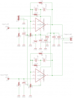
DJNUBZ - here is an implementation of the simple phono pre-amp in the LT1028 data sheet
http://cds.linear.com/docs/en/datasheet/1028fb.pdf (opens PDF, picture top of page 18)
that would fit in the top slot of an O2 amp in the taller B3-080 case. The board goes updside down from the image so the two electrolytics point downward. The power and ground wires into the O2 power, outputs go to the O2 input PCB holes, and inputs probably should go to RCA jacks mounted in the O2 amp front panel (that would fit with the taller B3 case).
I know you have wanted that phono pre-amp for a while. 🙂
Attachments
Last edited:
Hi all! I want to make a custom o2 that is as small as possible (only using batteies) so i want to ask if the filter section for batteries is really need or can i omit it? Like in the Grado Ra1, there are no filter capacitors too.
You can use SMD ceramic capacitors while still keeping the pcb size small.
If you are planning to omit PM ckt all together you will loose protection from low battery situation and power ON/OFF thump.
o2 inspired smd headphone-
http://www.diyaudio.com/forums/headphone-systems/236680-dual-o2-inspired-smd-headphone-amp.html
Last edited:
Hello all,
I'm a starting diy-artist and building the o2 amp+dac. I'm trying to make it desktop version: RCA input +1/4" output + (both panel mounted). The AC-input will also be panel mounted (so that it can be placed into the backpanel). So, my problem is my inexperience and lack of good instructions. I've made the O2 ready excluding the RCA, 1/4" socket, power input and the DAC. But now I'm unsure how should I solder the wires between the sockets and the board.
Could some either give me direct instructions or a link or help me in some other way? I'm sure these things have been discussed over before but I can't find any.
I've got these O2 Headphone Amplifier Desktop Kit but I haven't got the panel mounted AC-socket yet. (The amp will be fitted into the bigger B3-080 case)
Thanks alot!
Hi,
I've just assembled the O2 everything works fine however, when I increase and decrease the volume, some fuzz/static can be heard(only when nothing is playing though). Anyone know why this happens?
I've just assembled the O2 everything works fine however, when I increase and decrease the volume, some fuzz/static can be heard(only when nothing is playing though). Anyone know why this happens?
Assuming you used all the parts as per BOM and have an AC coupled source, it's got to be a scratchy pot. Not sure whether there are any fakes of RK09s around, maybe just a bad apple.
....Could some either give me direct instructions or a link or help me in some other way? I'm sure these things have been discussed over before but I can't find any....
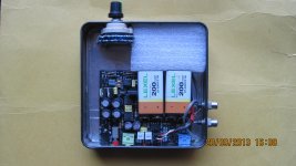
I can upload some more snaps of my O2 to help you out with RCA, 1/4 H/P, e.t.c. connection or PM you.
Attachments
Last edited:
Sorry if this is to OT but I broke down and ordered a VSPS 300 kit. I wanted to try playing with the 02 as an RIAA as I have a few extra boards laying around that I haven't decided what to do with just yet but you guys have convinced me to take the easier path.
AGDR thanks for posting that, I may still try playing around with that circuit at some point.
I think that the o2 circuit could be the basis a few other pieces. Considering it's measured performance, it would make a great preamp or phono preamp. Yes you would need to increase the gain and add the riaa filter but if you look at the VSPS, its not much more then an opamp and a few parts. With the o2 we have 2 gain stages to work with.
Steps for RCA connections
@sallau
Before proceeding-remove any batteries / AC power.
Steps for RCA connections-
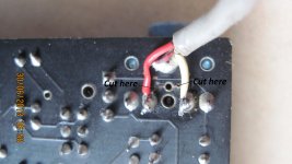
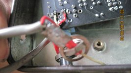
1. Carefully cut the GND track joining 3GND & 4GND using a sharp knife. Use continuity meter to verify that there is no continuity between points GND & 3GND or GND & 4GND.
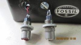
2. Strip stereo shielded cable & solder one of the inner two wires to point 3GND & the other wire to 4GND. Usually RED is LEFT CH. & WHITE is RIGHT CH. The outer copper mesh /shield is common GND. The end result should be something like image01.
3. Solder the inner pin of each RCA connector to the respective RED & WHITE wire. The outer “ring” of the RCA connector is common GND.
@sallau
Before proceeding-remove any batteries / AC power.
Steps for RCA connections-
1. Carefully cut the GND track joining 3GND & 4GND using a sharp knife. Use continuity meter to verify that there is no continuity between points GND & 3GND or GND & 4GND.
2. Strip stereo shielded cable & solder one of the inner two wires to point 3GND & the other wire to 4GND. Usually RED is LEFT CH. & WHITE is RIGHT CH. The outer copper mesh /shield is common GND. The end result should be something like image01.
3. Solder the inner pin of each RCA connector to the respective RED & WHITE wire. The outer “ring” of the RCA connector is common GND.
Attachments
Last edited:
- Home
- Amplifiers
- Headphone Systems
- The Objective2 (O2) Headphone Amp DIY Project