That's right Eva! +\- 82V full bridge 1.5V lose IGBT, with MUR6060CT for positive supply and 4 MUR1620CT for negative side supply, but dont forget that the output coil work only at positive or negative current mode because it's BD, so only positive or negative pulse pass trought the output filter. saturation is not a probleme here...You need to know why? What this will do if the output inductor ''filter'' only positive pulse for positive output or only negative pulse for negative output...Think about this! Yes the core sature at hight power, about 80% full power, but I dont care because of the type of modulation! Class BD is not obtain by some ''mechanical'' way as crown or all other full bridge configuration, but ''electronicaly'' by the modulator! So saturation have no effect otherwise to stress a bit the output capacitor...But be assure I have take this in consideration when I have design the amplifier!
By the way, Try to think a bit more evolutive before to make ''old school'' comment like this!
fredos
www.d-amp.com
By the way, Try to think a bit more evolutive before to make ''old school'' comment like this!
fredos
www.d-amp.com
Hello kartino
Current draw by the model DLS 3000 is 15.2A at 120V, at 1\3 of full power, both channel used at the same time. So maximum primary current of the transformer is about 6A...Why people stress as much with this? Maximum current when 100% power is provided by each channel is over 16A at the primary, but this is a abnormal condition, because in no way music can cause this condition for long time. So means current is about 6A. At secondary, current can reach about 12A on each side of transformer, but #12 litz wire is used. At 100% each side of transformer current is 42A , but same condition occure. Just dont forget, for certification purpose, only 1\3 of maximum power is used!
Fredos
www.d-amp.com
Inductor saturation has the same undesirable effects despite the modulation scheme empolyed. Furthermore, in a half bridge during continuous mode operation there is absolutely no difference between class D and class BD from the inductor point of view.
Anyway, dont worry about the output capacitor when the inductor saturates, the switching devices (or even the tweeters) will blow first 😉 You know, a saturated inductor behaves just as if the core was removed leaving the resulting air-cored coil (with 100 times less inductance) 😀😀😀
Where is the litz wire? 😀
Eva said:Anyway, dont worry about the output capacitor when the inductor saturates, the switching devices (or even the tweeters) will blow first 😉 You know, a saturated inductor behaves just as if the core was removed leaving the resulting air-cored coil (with 100 times less inductance) 😀😀😀
Hi Eva,
In India, we donot have access to high quality ferrites cores for high frequency operation ,thus making us rely on Air-core inductors...instead....
Is there any other way exist to solve EMI problems in Air core inductors ...does shielding helps them in reducing EMI generation....
regards,
K a n w a r
fredos said:
Current draw by the model DLS 3000 is 15.2A at 120V, at 1\3 of full power, both channel used at the same time. So maximum primary current of the transformer is about 6A...Why people stress as much with this? Maximum current when 100% power is provided by each channel is over 16A at the primary, but this is a abnormal condition, because in no way music can cause this condition for long time. So means current is about 6A. At secondary, current can reach about 12A on each side of transformer, but #12 litz wire is used. At 100% each side of transformer current is 42A , but same condition occure. Just dont forget, for certification purpose, only 1\3 of maximum power is used!
Fredos
Hi Fredos,
It is True that music signal donot draw as much as current in comparision to steady Sinewave signal, but I think its not even a good thing to test your amp with 1/3 of its maximum power.
Many Companies QSC, CrestAudio, Peavey, Crown rate their amp this way at 1/3 maximum power but ,I think its not a good thing, If the amp is rated at 3KW Continuous , then it must be capable of delivering its rated maximum power to the load for sustained long periods, not for short brusts alike in music-signals...
Note: If you Test your Amp with Plain Female vocal singing Signal then it would draw more current just like a continuous sinewaves , compared to any Bass Transient signals you ever heard....in music signals.
My Class-D amp is rated at 2 X 1200W @ 2ohms Continuous and its capable of delivering its maximum power with any Sinewave ranging from 10Hz to 20KHz , without any thermal tripping for continuous 24 Hours... The Output Mosfets were IRPF260N
in Half Bridge topology....
regards,
K a n w a r
hi,
I like your amp's spec, Kanwar, that's why the rated is RMS not as abrevation as "rated music square".
Anyway I see lots of statement that and amps is an amplification device, no matter what signal. OK we are limited as "audio amplifier" that of course for produce music. But what kind of music? We have lots of music from classic to hardcore. So if we buy amps shall we specify for what kind of music?
Then we have an answer, OK this amps is for all kind of music, the brabd is Workhorse, it is India's technology. It's rated 2 X 1200W
Hello Kartino,
Yes , Its India's First ever Class-D amp in Pro-Audio amplifiers....🙂
In my view amps must be rated at their full maximum power for sustained periods not for short intervals..
regards,
K a n w a r
Then we have an answer, OK this amps is for all kind of music, the brand is Workhorse, it is India's technology. It's rated 2 X 1200W
Yes , Its India's First ever Class-D amp in Pro-Audio amplifiers....🙂
In my view amps must be rated at their full maximum power for sustained periods not for short intervals..
regards,
K a n w a r
Hi Workhorse
Nobody prevents you from using gapped E ferrites, the useful range of operation of standard low frequency SMPS materials will be extended greatly as the gap is made longer. You don't even need to order them gapped, you may insert pieces of plastic or PCB material to form an uniform gap of the desired length on all core legs. I tried N27 cores at 100Khz that way and they ran cold (because most of the hard job is done by the air inside the gap).
Forget about air cored inductors (except in case you want to confine each one into a thick copper box, which would also change inductor parameters) and consider flux bands with the gapped ferrites. That's the only way to avoid having the switching waveform being induced into every circuit in the nearhood (and thus demodulated). Note that the flux band changes completely the parameters of the gapped inductor, so it has to be designed taking that into account (funny).
BTW: I won't believe you until I see some pictures.
Well, now I have to believe you, but where is the output filter? which switching devices are you employing and which supply voltages?
You don't have much choices with air cored inductors. If you place it in the PCB near the rest of the components, the stray magnetic field will cause induction into all the tracks and components (except if you place the coil in the right axis, or make a dipole or shape it as a toroid)... If you place it away from the PCB, the wire carrying the switching waveform will become the antenna of a nice AM/FM transmitter due to coil capacitance...
I feel than in class D it's not hard at all to get a working design, it's not even hard to make it reliable, the hard part is to make it quiet.
Hi, Kanwar,
For experimenting, maybe you can experiment with Ferrite cores from TV flyback? There should be many broken TV's, there are ferrite core inside the Flyback transformer. I don't know if the spec will meet your design, though.
For experimenting, maybe you can experiment with Ferrite cores from TV flyback? There should be many broken TV's, there are ferrite core inside the Flyback transformer. I don't know if the spec will meet your design, though.
I guess they have bit different EMC/EMI-norms in India 😀Eva said:If you place it away from the PCB, the wire carrying the switching waveform will become the antenna of a nice AM/FM transmitter due to coil capacitance...
After I saw electrical installations in SE-Asia I would´nt be supprised of anything. 😱
Hello Eva
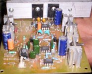
Take a closer look to the output coil of the power amp...That's a #12 litz wire....On micrometal ''blue'' core! Ran bit warm at full power, but cold with no signal!
WorkHorse
Maximum continuous power is rated for 15 minutes, but by experience, a power amp that handle continuous power for about 2 minute and 1/3 maximum power for 8 hours will play music all night long into clipping with no probleme! I have over 100 amplifier installed in lot of club in montreal (and over 600 around the world) and I dont have any probleme anywhere! The worst place was a the Parking nightclub, 2 D-Amp 4000 and 2 D-Amp 8000 was in a rack over 2 VZ 3600 of Crown that heat my D-Amp a lot, and I never get any probleme their, and I can told you that the amplifier is tortured a lot with lot of international DJ that always try to push the sound system over the ears pain treshold!
The good news is that at this time, booth of the VZ 3600 have blow fews time....So the result of the way I burn-in my amplifier is right, I think...
Fredos
www.d-amp.com
lumanuaw:
When you use a considerable gap, ferrite material choice is much less important because the core is just a "flux line collector" and permeability becomes only dependent on the length of the gap. Scrapped ferrites from TV flybacks (also the one from power supply) and from PC power supplies are fine. However, TV flybacks tend to come potted...
mzzj:
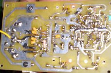
They should be far more tolerant to EMI in these countries, imagine the current spikes from two standard high voltage high current MOSFETs, one switching over the heavily conducting body diode of the other. Imagine these spikes flowing though that single sided PCB and causing the corresponding voltage drop spikes on the capacitors and the tracks. Now imagine these (unfiltered) voltage spikes, both differential mode and common mode, leaving the PCB through amplifier wiring and propagating to the outer world (PCB traces are usually not long enough to be efficient antennas, but wires definitely are). It's gorgeous!! 😀😀😀
Yesterday I finally etched a nice double sided PCB for the prototype in which I'm currently working. I have managed to reduce three fold the amplitude of the spikes radiated by everything, and I killed absolutely all the ringing. To my surprise, now it's the radiation from stupid things such as output inductor leads (and the leads of my magnetic snubber due to a clumsy designed coil former) what dominates. (BTW: With the magnetic snubber the spikes radiated by switching over the conducting diodes become similar or smaller than the own spikes caused by the dI/dt of the diodes turning back on at the end of each cycle 😀😀 )
fredos:
I mean litz wire in the SMPS transformer. It's obviously wound with thin hookup wire.
When you use a considerable gap, ferrite material choice is much less important because the core is just a "flux line collector" and permeability becomes only dependent on the length of the gap. Scrapped ferrites from TV flybacks (also the one from power supply) and from PC power supplies are fine. However, TV flybacks tend to come potted...
mzzj:
They should be far more tolerant to EMI in these countries, imagine the current spikes from two standard high voltage high current MOSFETs, one switching over the heavily conducting body diode of the other. Imagine these spikes flowing though that single sided PCB and causing the corresponding voltage drop spikes on the capacitors and the tracks. Now imagine these (unfiltered) voltage spikes, both differential mode and common mode, leaving the PCB through amplifier wiring and propagating to the outer world (PCB traces are usually not long enough to be efficient antennas, but wires definitely are). It's gorgeous!! 😀😀😀
Yesterday I finally etched a nice double sided PCB for the prototype in which I'm currently working. I have managed to reduce three fold the amplitude of the spikes radiated by everything, and I killed absolutely all the ringing. To my surprise, now it's the radiation from stupid things such as output inductor leads (and the leads of my magnetic snubber due to a clumsy designed coil former) what dominates. (BTW: With the magnetic snubber the spikes radiated by switching over the conducting diodes become similar or smaller than the own spikes caused by the dI/dt of the diodes turning back on at the end of each cycle 😀😀 )
fredos:
I mean litz wire in the SMPS transformer. It's obviously wound with thin hookup wire.
Eva said:Well, now I have to believe you, but where is the output filter? which switching devices are you employing and which supply voltages?
You don't have much choices with air cored inductors. If you place it in the PCB near the rest of the components, the stray magnetic field will cause induction into all the tracks and components (except if you place the coil in the right axis, or make a dipole or shape it as a toroid)... If you place it away from the PCB, the wire carrying the switching waveform will become the antenna of a nice AM/FM transmitter due to coil capacitance...
I feel than in class D it's not hard at all to get a working design, it's not even hard to make it reliable, the hard part is to make it quiet.
EVA,
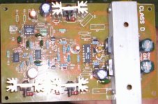
The Output Inductor is Offboard....
I would Try the Ferrite cores with Gap in between them and post the results in couple of days...
Devices are IRFP260N , supplies at +-85VDC
fredos said:WorkHorse
Maximum continuous power is rated for 15 minutes, but by experience, a power amp that handle continuous power for about 2 minute and 1/3 maximum power for 8 hours will play music all night long into clipping with no probleme! I have over 100 amplifier installed in lot of club in montreal (and over 600 around the world) and I dont have any probleme anywhere! The worst place was a the Parking nightclub, 2 D-Amp 4000 and 2 D-Amp 8000 was in a rack over 2 VZ 3600 of Crown that heat my D-Amp a lot, and I never get any probleme their, and I can told you that the amplifier is tortured a lot with lot of international DJ that always try to push the sound system over the ears pain treshold!
The good news is that at this time, booth of the VZ 3600 have blow fews time....So the result of the way I burn-in my amplifier is right, I think...
Fredos
www.d-amp.com
Thats good fredos
Workhorse, I recommend you to build a simple adjustable switching circuit allowing to measure inductances and saturation currents, if you don't have something similar already. Standard LCR meters and the like are not suited at all for gapped ferrites (or iron powder), they will always provide an erratic measurement.
- Status
- Not open for further replies.
- Home
- Vendor's Bazaar
- The news D-Amp DLS3000....