Brian, Thanks for the link.. I'll give them a try too...
In the case someone is scrutinizing the flg version of Circlotron, I have corrected a few errors in the previous schez. I would not want someone being confused for a while before they asked me about one of them errors....
I am designing the Output (including those 10,000uFs)and output bias components all on 1 board that mounts to a P-IV heatpipe. The driver portion, excluding the load Rs I have layed out on a little square board the size of the 4 TO-220s and it mounts to a normal Pentium H.S. along with 2 TO-220 Caddok load Rs, without a fan. I probably won't get in much bench testing for a few months though...
Attachments
Regarding the 2SK2013/2SJ313
Borbely's prices for these Toshiba devices aren't that bad, compared to other items he offers. Nikko in the UK has them for 40% less.
It's likely that you can get them from Mark5 and Dial, besides Fibra Brandt.
Overhere, i can get the 2SK2013/2SJ313 delivered in 1 day, but just ordering 1 from those places is likely to cost $25. With higher order numbers the unit price remains not attractive, but there are other places that deliver within a week which are much cheaper. Patrick, if you can get them straight from Japan i'm very interested in knowing the unit rate for those.
The OSF and SSF distinction is elegantly put, Mr Rollins, as usual.
Fibra Brandt does list the 2SK389 etc. but does not list the 2SK2013/2SJ313.
I have 2SK389s and 2SJ109 in BL, and 2SK170/2SJ74 in GR. I have some of the "VI" LSK389s and LSK170s (although they call them "C" instead of "VI").
EUVL,
You said to contact you about a Japanese source for the 2SK2013/2SJ313, but your e-mail is turned off. I'm interested.
flg,
Motorola/On Semi has the 2N5457-59 and 2N5460-62 small signal JFETs. (I think I got those numbers right.) I've had good results with the 2N5457 before, but have not used the higher current parts, nor have I used the P-ch devices so I have no opinion on those. They have others, I believe, but I can't remember what offhand.
All,
Don't hold me to it, but I'm going to try to have another output stage version posted by the end of the week. I've got about half a ton of scribbled notes and hand-drawn schematics that I need to go through and transcribe into something tolerably readable. I've gotten myself embroiled in a new front end and still need to get some writing done before my editor forgets me.
Grey
They seem fine to me. Someone had posted something earlier that seemed to indicate that they weren't happy with them, but didn't specify why.
Grey
Grey
Nothing wrong with LSK389, except :
a) they are not improved versions of Toshiba as they claim to be;
b) they are not package / pin compatible if you already have a layout for Toshiba;
c) they are not cheap (at least in Europe double the price);
d) they are not widely available; again in Germany only available from distributor at volume.
And there is still enough 2SK389s around.
Patrick
And they do not seem to be able to offer P-JFETs, if you have a complementary circuitry. So you still need 2SJ109, which appears to be much more difficult to get.
Patrick
Patrick
ON Semi has the P JFET 2N5460-62 and I have used them... I am a audibly challenged person (deaf in 1 ear can't hear out of the other😀 ) So, commenting on the nuances of it's sound would not be cool. But they work like the datasheet says, let me say that... And, I use them first, whenever I need a P-JFET... I guess the other one was 5457-59? I don't know, Havent tried, and as usual I don't think it is actually a complement... I have tried something like a 2N5487??? RF stuff!
Another output stage??? Cool... Would'nt be a ZV9-T type circuit would it??? Hey, I needed to think Power JFET to be true to the thread😀 😀 😀
I am home at lunch, digging through my boxes for the parts for the Circlotron by flg board. Moving slowly but making progress...
Another output stage??? Cool... Would'nt be a ZV9-T type circuit would it??? Hey, I needed to think Power JFET to be true to the thread😀 😀 😀
I am home at lunch, digging through my boxes for the parts for the Circlotron by flg board. Moving slowly but making progress...
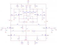
Not meant to distract from Grey's circuit, but only for the sake of discussion; how about this ?
Two stage, Cascoded JFET LTP input, X-feedback. Very simple.
(It is basically the circuit from Circlomanen, except that I toke out the source feedback, and use a LTP at the first stage. Of course one can change the power devices to Cascoded Power JFETs.)
Any drawbacks ?
Patrick
Two stage, Cascoded JFET LTP input, X-feedback. Very simple.
(It is basically the circuit from Circlomanen, except that I toke out the source feedback, and use a LTP at the first stage. Of course one can change the power devices to Cascoded Power JFETs.)
Any drawbacks ?
Patrick
Attachments
I am always bothered by the need to attach the center of
the load to a ground, in this case the 56 ohm 10 watt resistors.
the load to a ground, in this case the 56 ohm 10 watt resistors.
> I am always bothered by the need to attach the center of
the load to a ground, in this case the 56 ohm 10 watt resistors.
If I remember correctly, we have something similar in Aleph-X with 33ohm (100ohm) power resistors ?
I think, if I am correct, one cannot avoid that in case of a circlotron. In Grey's power stage schematics, I think he tied each output to ground with 1k. I just put down 56 ohm for no specific reason other than that it is the value I used for Aleph-X with same bias. But I guess we don't really have absolute DC in a circlotron ??
Patrick
Actually not, in the sense that I can dispense with them and
have to compensate DC offset some other way. Ground is
still the same thing to everybody in the circuit. Here, you create
a virtual ground by way of dividing the voltage across the load
by 2. I didn't say that it didn't work, I said that I was not
comfortable with it.
have to compensate DC offset some other way. Ground is
still the same thing to everybody in the circuit. Here, you create
a virtual ground by way of dividing the voltage across the load
by 2. I didn't say that it didn't work, I said that I was not
comfortable with it.
I have read in other published Circlotron info that the value of these resisters was to be 6-8 X the load value >>> 56 ohm... I am also interested in the important criteria for optimizing this value ???
In simulations of my circuit, values up to 1k ohms or so show slightly improved THD. My board has 2 300 ohm 2 Watts to Gnd across the load. I beleive my posted schematic had 220 ohms to Gnd.
In simulations of my circuit, values up to 1k ohms or so show slightly improved THD. My board has 2 300 ohm 2 Watts to Gnd across the load. I beleive my posted schematic had 220 ohms to Gnd.
O.K. That having been said, You need the Gnd ref to turn on the FET but also, any imbalances, unmatched components, etc. will create currents to Gnd through these Rs. Then you have hotter Rs and DC potential devloping across the load... So, smaller is better??? But it will cut into your output power, so bigger is better ??? Will they effect damping??? Apparent source R??? Something else I should be thinking about???
Well, you pin it down - smaller is better, and bigger is better.
56 ohms is probably about as good as anything. Personally
I solved the problem by transformer coupling the inputs, so
that the need for a ground vanishes, but that increases the
expense and you have to put up with tranformer distortion
(although it appears that some people like it that way)
😎
56 ohms is probably about as good as anything. Personally
I solved the problem by transformer coupling the inputs, so
that the need for a ground vanishes, but that increases the
expense and you have to put up with tranformer distortion
(although it appears that some people like it that way)
😎
>I didn't say that it didn't work, I said that I was not comfortable with it.
Would you be kind enough to give us some hints to the reasons behind ?
> Actually not, in the sense that I can dispense with them and have to compensate DC offset some other way.
Let's suppose we take them out.
The driver stage will still be happy, as the gate is driven by current from the LTP. The speaker does not know what ground is, so still OK. The feedback resistors to the LTP might see a floating common mode voltage, so perhaps creat a virtual ground there ? Would the 100k to ground at the JFET gates be sufficient for that ?
> I solved the problem by transformer coupling the inputs, so that the need for a ground vanishes.
That does not seem to solve the problem with floating common mode voltage across the 100k resistor, or am I on the wrong track ? Or are you suggesting that we have no ground at all in the circuit ?
And I don't like transformers. Otherwise I would have been building tube amps. : )
Patrick
Hi Patrick,
During waiting for NP's reply to your questions . . .
I do not know why there is a connection from the mid-point of the two 56R to the ground. For me, the mid-point is already a vertual ground without that connection. Meanwhile, the speaker load has also a vertual ground in the mid-point so that probably the two 56R are no need . . . ?
Couldn't we adjust R21 for DC offset control . . . ?
Regards
jh6you,
How could we address you by name ?
> Couldn't we adjust R21 for DC offset control . . . ?
Ideally not, as R21 determines open loop gain.
You can adjust differential DC by TR2 at the source of the diff pair. But that is not the point.
I guess I have actually tried to incorporate a means of controlling absolute DC -- the 2x12.4k resistors connecting both outputs to the diff pair current source output, same as in Aleph-X.
But suppose we do not tie the outputs to ground, and they both float to say +12V wrt Gnd at no signal. Speaker sees nothing, but the JFETs get extra 1mA each, increasing bias at both power FETs through R21/R22, which when perfectly match balance themselves out. And we can get to uncontrolled bias instability.
At hindsight, maybe they should be removed, as the cicuit is not push pull, and there is no need to feedback absolute DC.
I shall try to post an updated schematics later.
Patrick
- Status
- Not open for further replies.
- Home
- Amplifiers
- Pass Labs
- The New-Tron