Re: Re: Re: Re: Re: Re: Re: Re: TL431
Hi Elso,
I use a cascaded voltage regulator, whereas the second section needs adjustment to minimise the noise.
The circuit stems from power supplis used in spectrum analyres, where they need low noise for the local oscillator........
Low noise is realy required for proper performance of a(ny) clock, and yes, 5 nV/Sqrrt Hz is more than 30 db more quiet than an LM317T.
best regards
Elso Kwak said:
Dear Guido,
Thanks for the reply.
Now the sharp-eyed reader sees a TO-220 voltage regulator, some caps and a pot on your circuit and is wondering how to achieve 5nV/Sqrrt Hz noise?
😕
Don't feel obliged to share the schematic....😉
Best regards,
Hi Elso,
I use a cascaded voltage regulator, whereas the second section needs adjustment to minimise the noise.
The circuit stems from power supplis used in spectrum analyres, where they need low noise for the local oscillator........
Low noise is realy required for proper performance of a(ny) clock, and yes, 5 nV/Sqrrt Hz is more than 30 db more quiet than an LM317T.
best regards
Hi Peter,
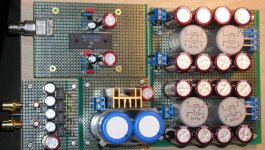
You build nice things even when it's on temporary boards.
Nise transformers too!
Now the comparation with other DAC's.
I can't wait to hear the audible result from you.
Audiofanatic😉 Really nice work! You always do this to me
You build nice things even when it's on temporary boards.
Nise transformers too!
Now the comparation with other DAC's.
I can't wait to hear the audible result from you.
Audiofanatic😉 Really nice work! You always do this to me
Hi Paul,
Sorry for not giving you my email address. Please send the scans to denniskmwong@ctimail.com.
Thank you very much for your help!
Best regards,
Dennis
Sorry for not giving you my email address. Please send the scans to denniskmwong@ctimail.com.
Thank you very much for your help!
Best regards,
Dennis
Re: Re: Re: Re: Re: Re: Re: Re: Re: TL431
Something along these lines perhaps? (I overlooked the TO-92 small transistor)
http://www3.sympatico.ca/add.automation/spice/ripple.htm
(A good listener only needs half a word 😉 )
😉 )
Best regards,
Hi Guido,Guido Tent said:
Hi Elso,
I use a cascaded voltage regulator, whereas the second section needs adjustment to minimise the noise.
The circuit stems from power supplis used in spectrum analyres, where they need low noise for the local oscillator........
Low noise is realy required for proper performance of a(ny) clock, and yes, 5 nV/Sqrrt Hz is more than 30 db more quiet than an LM317T.
best regards
Something along these lines perhaps? (I overlooked the TO-92 small transistor)
http://www3.sympatico.ca/add.automation/spice/ripple.htm
(A good listener only needs half a word
😉 )Best regards,
schematic third dac
The schematic is too big for attaching on this forum. I want to mail it to you but you have to leave a mailadress since I can't attach anything with the Mail function of Diyaudio.com.
So for the last time, leave you mailadress in a way like this to avoid spamming:
Jean-Paul,
I to would like receive the artical.
cdurnall_nospam@yahoodotcom
Many thanks in advance.
Colin
Hi Elso,
What voltage do you prefer with TDA1543, it seems that JP likes 5V better😉
I also noticed strange behaviour of that chip. I tried to adjust the regulator according to current draw (didn't have I2S connected to DAC yet), but somehow I couldn't go more than 2.5V at DAC's pins (although output from reg was 8V). I also tried a single chip, connected directly to reg PS and the result was the same (pin 4: ground, pin 5: +6V). My first config is using 4 chips in parallel and I have 400ohm resistor at Vref. pin.
TDA1543 Questions
Hi Peter,
I concur with Jean-Paul. I like +5V the most.
I did not notice the "strange behavior" of the chip. Perhaps try again with I2S signals connected. But I only tried LM1086, MC7805 and my triple Darlington circuit.
😕
Peter Daniel said:Hi Elso,
What voltage do you prefer with TDA1543, it seems that JP likes 5V better😉
I also noticed strange behaviour of that chip. I tried to adjust the regulator according to current draw (didn't have I2S connected to DAC yet), but somehow I couldn't go more than 2.5V at DAC's pins (although output from reg was 8V). I also tried a single chip, connected directly to reg PS and the result was the same (pin 4: ground, pin 5: +6V). My first config is using 4 chips in parallel and I have 400ohm resistor at Vref. pin.
Hi Peter,
I concur with Jean-Paul. I like +5V the most.
I did not notice the "strange behavior" of the chip. Perhaps try again with I2S signals connected. But I only tried LM1086, MC7805 and my triple Darlington circuit.
😕
Re: TDA1543 Questions
Hi all,
If you increase the voltage, you will increase the cross-current through all inverters and flipflops. In turn, the groundbounce will increase (dramatically) so the on chip noise, and induced voltage in I/O signals will increase rapidly
Decreasing the voltage will slow down the gates, and mismatch switching levels with internal / exetrnal I/O
Somewhere an optimum will be........
Guido
Elso Kwak said:
Hi Peter,
I concur with Jean-Paul. I like +5V the most.
I did not notice the "strange behavior" of the chip. Perhaps try again with I2S signals connected. But I only tried LM1086, MC7805 and my triple Darlington circuit.
😕
Hi all,
If you increase the voltage, you will increase the cross-current through all inverters and flipflops. In turn, the groundbounce will increase (dramatically) so the on chip noise, and induced voltage in I/O signals will increase rapidly
Decreasing the voltage will slow down the gates, and mismatch switching levels with internal / exetrnal I/O
Somewhere an optimum will be........
Guido
Re: Re: TDA1543 Questions
The optimum is at +5V as advised by the manufacturer.
The difference with 8V is not as dramatic like the picture you are painting above. Fedde prefers 8V, and many others.
🙄
Guido,Guido Tent said:
Hi all,
If you increase the voltage, you will increase the cross-current through all inverters and flipflops. In turn, the groundbounce will increase (dramatically) so the on chip noise, and induced voltage in I/O signals will increase rapidly
Decreasing the voltage will slow down the gates, and mismatch switching levels with internal / exetrnal I/O
Somewhere an optimum will be........
Guido
The optimum is at +5V as advised by the manufacturer.
The difference with 8V is not as dramatic like the picture you are painting above. Fedde prefers 8V, and many others.
🙄
Re: Re: Re: Re: Re: Re: Re: Re: Re: TL431
Hi Guido,
As a experiment I replaced the LM431's in my clock-supply (+/-5V) by much lower noise LM329's. It is similar to Cuno Snoerens circuit that is lifted from the TI-datasheet.
Bass was slightly less powerfull but the general soundpicture was the same.
So I still don't buy it that lower noise clock-supply is better sound.
I quickly reinstalled the LM431's!
From the endless experiments I have done with various versions of my clock and powersupplies I learned that the schematic of the clock-circuit and component choice are the most important parameters.
Best regards,
😎
Guido Tent said:
Hi Elso,
I use a cascaded voltage regulator, whereas the second section needs adjustment to minimise the noise.
The circuit stems from power supplis used in spectrum analyres, where they need low noise for the local oscillator........
Low noise is realy required for proper performance of a(ny) clock, and yes, 5 nV/Sqrrt Hz is more than 30 db more quiet than an LM317T.
best regards
Hi Guido,
As a experiment I replaced the LM431's in my clock-supply (+/-5V) by much lower noise LM329's. It is similar to Cuno Snoerens circuit that is lifted from the TI-datasheet.
Bass was slightly less powerfull but the general soundpicture was the same.
So I still don't buy it that lower noise clock-supply is better sound.
I quickly reinstalled the LM431's!
From the endless experiments I have done with various versions of my clock and powersupplies I learned that the schematic of the clock-circuit and component choice are the most important parameters.
Best regards,
😎
Re: Re: Re: TDA1543 Questions
Hello Elso,
What I described are measurable effects, in the application. The main question is how these effects affect the sonic performance.
I have not carried out audio measurements on chips at higher voltages, I just pointed out that some parameters change dramatically when increasing the supply.
Unfortunately most manufacturers info stops at 5,5 V.......
best regards
-
Elso Kwak said:
Guido,
The optimum is at +5V as advised by the manufacturer.
The difference with 8V is not as dramatic like the picture you are painting above. Fedde prefers 8V, and many others.
🙄
Hello Elso,
What I described are measurable effects, in the application. The main question is how these effects affect the sonic performance.
I have not carried out audio measurements on chips at higher voltages, I just pointed out that some parameters change dramatically when increasing the supply.
Unfortunately most manufacturers info stops at 5,5 V.......
best regards
-
Re: TDA1543 Questions
Is it the one based on Audio Note supply? Which one do you prefer?
Elso Kwak said:
my triple Darlington circuit.
Is it the one based on Audio Note supply? Which one do you prefer?
Question to Pedja and Jean-Paul please!
As mentioned by both of you, 3.3nf cap is only suitable for 1k resister with 5V supply and 2.2nf should be used for 1.69k resister in 8V supply.
I just noticed from Kusunuki's third article in MJ that he used a 0.033uf cap in parallel with a 3300pf cap (i.e. 0.0363uf) in this location. Do you think he used the cap too tall? In fact, I don't know the purpose of this cap, would you please explai a bit on it.
Thanks a lot in advance!
Dennis
Re: Re: TDA1543 Questions
Hi Peter,
Yes that one, I prefer most.
Later I use a inductor with less than 1 Ohm DC-resistance and two 4700µF caps added after the coil (parallel C10). Still using it.
Did you get your DAC working yet? The bare wires don't shortcircuit on the PCB of the TDA1543? Just a idea...
🙂
Peter Daniel said:
Is it the one based on Audio Note supply? Which one do you prefer?
Hi Peter,
Yes that one, I prefer most.
Later I use a inductor with less than 1 Ohm DC-resistance and two 4700µF caps added after the coil (parallel C10). Still using it.
Did you get your DAC working yet? The bare wires don't shortcircuit on the PCB of the TDA1543? Just a idea...
🙂
Attachments
Supply for TDA1543
Hi,
I also designed a very simple supply using the TL431 as a shuntregulator fed by a active constant current source. I did not try this circuit myself but the guy who I did this for was very enthusiastic about it.😉
The diode is a red LED giving a 1.6 minus one Vbe drop = 1V over the 20 Ohm resistor.
The current is V/R= 1/20= 50mA. Suited for one TDA1543.😎
On second thought it may be wise to increase the current slightly as with 50mA there is not left any current for the TL431 as the TDA1543 draws 50mA typically on 5V supply.😎
Attachments

Re: Re: Re: Re: TDA1543 Questions
And how do these measurable effects have a impact on sonics?😕
Most DAC chips don't take a voltage as high as 9V gracefully like the TDA1543.
The max. for the TDA1545A is 5.5V.
Best regards,
🙄
Hello Guido,Guido Tent said:
Hello Elso,
What I described are measurable effects, in the application. The main question is how these effects affect the sonic performance.
I have not carried out audio measurements on chips at higher voltages, I just pointed out that some parameters change dramatically when increasing the supply.
Unfortunately most manufacturers info stops at 5,5 V.......
best regards
-
And how do these measurable effects have a impact on sonics?😕
Most DAC chips don't take a voltage as high as 9V gracefully like the TDA1543.
The max. for the TDA1545A is 5.5V.
Best regards,
🙄
Re: Re: Re: Re: Re: TDA1543 Questions
Elso
I never caried out perception on this kind of tests.
I did however measure higher jitter and groundbounce voltages on various (non audio) chips.
I wouldn't be surprised if the (non harmonic!) distortion rises with supply voltage.
I have no test vehicle lying around.
If you use 9V on a 1543, I'd suggest to by some extra samples for life
🙂
best regards
Elso Kwak said:
Hello Guido,
And how do these measurable effects have a impact on sonics?😕
Most DAC chips don't take a voltage as high as 9V gracefully like the TDA1543.
The max. for the TDA1545A is 5.5V.
Best regards,
🙄
Elso
I never caried out perception on this kind of tests.
I did however measure higher jitter and groundbounce voltages on various (non audio) chips.
I wouldn't be surprised if the (non harmonic!) distortion rises with supply voltage.
I have no test vehicle lying around.
If you use 9V on a 1543, I'd suggest to by some extra samples for life
🙂
best regards
If using reclocking circuit between CS8412 and TDA1543, what is a recommended clock frequency? I have a nice 27Mhz clock, but it seems that everybody's using higher freq. Would this one be OK?
Also, I'm using separate transformers and filtering for receiver and DAC. Where is the best point to connect grounds for both circuits? I assumed at PS caps, is it the good choice?
Also, I'm using separate transformers and filtering for receiver and DAC. Where is the best point to connect grounds for both circuits? I assumed at PS caps, is it the good choice?
Asynchronous Reclocking
Hi Peter,
Kusunoki uses a cantype 50 MHz oscillator.
I have tried various frequencies and found a higher frequency better. Of course the clock used for the reclocker should be low jitter. Low jitter is more important than the higher frequency. Circuit details in this clock are heard in the endresult: the sound.
I am still working on it...
When I was using the TDA1543 in a separate DAC I used two transformers one for digital and one for analog. The digital supply was for the digital section of the CS8412, resetcircuit, AD8561 inputcomparator, and the Asynchronous Reclocker. The Analog supply was used for the TDA1543, IV-converter and outputbuffer and PLL section of the CS8412. The +5V of the analog and digital supply are connected at the CS8412 by two 1N4148 diodes parallel head to back.
I have the digital and analog ground connected at the raw powersupply by a 2.2mH choke. The ground of the PLL section of the CS8412 is connected to the analog ground.
Using the low noise analog supply for the PLL of the DIR was one of the hints I got on AA.
The two diodes are straight from Kusunoki's paper. Jean-Paul did some "mailing". I have it too.🙂
Peter Daniel said:If using reclocking circuit between CS8412 and TDA1543, what is a recommended clock frequency? I have a nice 27Mhz clock, but it seems that everybody's using higher freq. Would this one be OK?
Also, I'm using separate transformers and filtering for receiver and DAC. Where is the best point to connect grounds for both circuits? I assumed at PS caps, is it the good choice?
Hi Peter,
Kusunoki uses a cantype 50 MHz oscillator.
I have tried various frequencies and found a higher frequency better. Of course the clock used for the reclocker should be low jitter. Low jitter is more important than the higher frequency. Circuit details in this clock are heard in the endresult: the sound.
I am still working on it...
When I was using the TDA1543 in a separate DAC I used two transformers one for digital and one for analog. The digital supply was for the digital section of the CS8412, resetcircuit, AD8561 inputcomparator, and the Asynchronous Reclocker. The Analog supply was used for the TDA1543, IV-converter and outputbuffer and PLL section of the CS8412. The +5V of the analog and digital supply are connected at the CS8412 by two 1N4148 diodes parallel head to back.
I have the digital and analog ground connected at the raw powersupply by a 2.2mH choke. The ground of the PLL section of the CS8412 is connected to the analog ground.
Using the low noise analog supply for the PLL of the DIR was one of the hints I got on AA.
The two diodes are straight from Kusunoki's paper. Jean-Paul did some "mailing". I have it too.🙂
- Status
- Not open for further replies.
- Home
- Source & Line
- Digital Source
- The new Nonoz II DAC page !!!