Recreating the Mysterious Synergy Crossover in DSP
I’ve been a fan of Danley’s speakers for many years. I’ve even very briefly heard the real thing, at their warehouse, but in the short time I couldn't make a judgement pro or con. I have had the good fortune to have, for about five years, sort of a “poor cousin,” the Yorkville Unity U15. Mine were bought used and had blown crossovers but (fortunately) good drivers. You could say these trashed transducers were a “York-vile,” but in fact were ideal for DIY experimentation.
As such, I converted them to active and have enjoyed them ever since. They are easily the finest sounding speakers I’ve ever owned, and I’ve owned quite a few.
Of course, using active crossovers (JRiver in my case) has many advantages: not the least is to tweak and EQ to taste. Mine have never sounded “bad,” but I wonder: how close can I get to the true Synergy crossover? A disadvantage is that I lack the best test gear. I have REW and an uncalibrated mic. Frequency sweeps no problem. But timing or phase? Unreliable. But are they necessary? For best results, perhaps, but can I get real close without? Maybe.
Danley (the man) is a treasure for DIY. Who else has given as much help, as many hints, as he has? In this “essay”, I’d like to try and figure out what one of his crossovers requires.
In the first place, it helps to know the basics of Unity/Synergy (these are, to me, almost the same, and in fact, they differ primarily in the sophistication of the crossover and perhaps the port shapes.) Danley accomplishes his “magic” with a passive crossover, clearly one carefully designed and tailored to each individual speaker model. Not the least of his “secret ingredients” are his non-standard slopes. But also (I expect) the need to provide delays between the drivers. The latter is easily supplied by timing adjustment on an active EQ.
This thread
[url]https://www.diyaudio.com/forums/multi-way/329112-unity-horn-time-alignment-workflow.html[/URL]
Provides much information on crossovers, indeed the best I’m aware of on diyaudio. I’ll quote selectively from here, relevant to my own project.
Clearly, my horn is already built so all I’m playing with are the crossover options. The Yorkville is well designed, at least as regards the mids “reaching” the “tweeter” (BMS4550). The stock HF x-over is 1250 Hz. My mid “cancellation notch” is about 1.9 KHz. The BMS4550 is rated down to 800 Hz. At higher outputs, I’m aware the CD is “happier” if it isn’t expected to play down to 800 Hz. Thus the Yorkville’s 1250 Hz, the SH50’s 1350 Hz x-over points. Yet, at least at first glance, it seems that Danley is crossing over much lower!
(RobWells, msg #21) quotes Danley: “A crossover hint. Next time you have your software open, model two band pass filters to make a pretend upper and lower speaker. Examine the phase response for each. Notice that the phase doesn’t approach zero until quite a ways above the low corners.
Our style xover ideally ends with a flat phase response like there was no crossover at all. So, what one can see is that if one were going to “shove” the two bandwidths closer together to knit them so that the phases were say around 90 degrees apart , that you have to be past the low corner of the upper driver. Also the less phase shift the corner has (shallower) the less rapidly the phase is changing”.
Here, I’m befuddled: yes, any driver (the BMS4550 in this case) will have a low corner, call it 800 Hz. It has a natural (acoustic) roll-off. But does Danley use this natural roll off? If so, how does he protect the delicate compression driver from unwanted lower frequencies?
Intuitively, I think I understand what he’s advocating: let’s consider the mid port’s natural low-pass behavior: in my case, at about 1.9 KHz. Sure, I can put an electrical filter there, it wouldn’t hurt anything if I left it out, but we are prone to unwanted “harmonics” of the ½ wave cancellation. We don’t want any output from mids > 1.9 KHz. So are we doing the same with the “tweeter” but as a high-pass? Sure, it can be done, and that’ll protect the CD somewhat, but again, how can you get a higher crossover frequency if you’ve set them already at the (in CD’s case) lower corner? Me is confused. OK, Tom, I’m baffled. Sure, your SH50 or whatever will have different crossover points, maybe not the BMS4550 (same CD, I think, as the Yorkville) but the mid’s ½ wave notch? Almost certainly different.
Can it be as simple as what I’m proposing here (e.g. my mids LP = cancellation frequency), and the “tweeter” HP at 800 Hz? I say “yes” because this uses the natural corners of each driver, and the electrical x-over is “protection.” But a frequency overlap of a whole octave? Well, why not? The phase is -- potentially -- wonderful in the middle of that range, but the phase is still going to be a dog’s breakfast at those corner frequencies, isn’t it? Perhaps the broad overlap smooths out the phases? Could be: the CD is well into its smooth phase operating range when the mids are getting sloppy, and vice versa.
I realize Danley does more: he still has to make the highs and lows meet up in time. He can do this with his secret crossover. I can (or should be able to) do this with simple delay.
“A changing phase is changing time.
This is why I have mentioned the lower response corner and phase of the bms driver, it makes it easier to do. If you examine the group delay for the sum and displace the upper driver to the rear, one can justify the GD to be equal. When you have the right electrical part and the right physical offset, it looks, acts, sounds like one driver covering that band. I can’t tell you what slopes to use because you end up with something with no name, it has to be adapted to the acoustic magnitude and phase responses of the sources. I can say that usually I can get away with something reaching a 4th order or higher electrical high pass for the compression driver.’ [Edited slightly].
Using a higher order to delay the highs a suitable time?
(Cask05 #23) writes: “Also, you will find that high-pass/low pass crossover filter frequency overlap will need to be increased using MEH designs. I find that using first order crossover filters automatically takes care of the phase/frequency and the polar coverage/frequency issues. I recommend first trying the high pass crossover frequency at about 50 Hz below the low pass point, as a start. You will need to iterate this to find the best overlap to use for your horn coverage angles and off-axis ports.”
The use of gapped crossover points is mentioned a few times. But again, what is the benefit, if these are far from the natural corners of the CD and mids, respectively? Those corners are set by physical constraints, you can’t change them. This is what is causing my brain to crash and reboot.
The first rule of Synergy Horns is:
We don't talk about the crossover.
But seriously, that's one of the reasons that I always refer to my random projects as "Unity Horns."
There's a significant difference between Synergy Horns and Unity Horns, and the difference is the crossover.
90% of the Synergy Horn projects I've seen online don't feature the Synergy Horn xover.
Interestingly the Synergy crossover is not described in the patent and is therefor not covered. This is especially interesting because the crossover is described as the main difference between Unity and Synergy horns. The only other difference is the smaller mid ports, which is covered by prior art.
Soldermizer, I believe you are on the right track. Shelve your two responses down 6dB and have them overlap at that level for an octave or more. That should do the trick. Because of horn loading and the eq required for a flat response you are already down a long way at 1KHz. Even use a little boost if necessary to extend the response of your drivers for a bigger overlap. You'll be amazed just how hard you can push that 4550 in a domestic environment.
I've done many MEH active and passive crossovers and this recipe does work.
OK let me add some hints.
If you take a look at the crossover of speakers from Dunlavy, Vandersteen, Dynaudio, and Thiel, you'll see that the high pass and the low pass crossovers are first order. By using first order crossovers and having the acoustic centers on the same vertical plane, your wavefront will be in phase.
For a while, Vandersteens were my reference speakers. Something that I liked about them is that the intelligibility is very good and the percussion is very good. If you listen to transients, they just sound noticeably better than a high order xover.
With my Vandersteens, the soundstage was basically located where the speakers are.
In a SH50, the diaphragm of the tweeter is about 11.5cm behind the woofer.
There's a few ways to deal with that physical gap:
* You could say 'screw it' and do nothing. Basically focus on getting the frequency response correct, and ignore the phase
* You could use DSP delay
* Or you could use a steep lowpass on the midbass.
For instance, 1487Hz is 23cm long. Each "order" of your lowpass introduces a delay of 90 degrees. Which means that if your low pass filter is 4th order and your high pass filter is 2nd order, the midranges will be delayed by 11.5cm.
Please go verify all of that in Vituixcad or XSim. I always get confused about the delay of high pass filters. I do know that low pass filters add 90 degrees of phase shift for every order. IE, the reason that a Linkwitz Riley 4th order low pass has flat response is because it delays the output by an entire wavelength.
In other words, if you moved the midbass of a speaker forward by an entire wavelength, and it was using a LR4 filter, it would be in-phase. (This assumes the tweeter has a low order filter.)
This stuff is painfully complex, and I think that most people who make speakers just aim for flat response and don't lose much sleep over the phase response.
To me, the reason that it's so NEAT is because you can wind up with a speaker where the drive units are as much as 30cm apart, but it's still in phase.
Subjectively, this yields a speaker where it's really difficult to tell where the soundstage begins and ends.
I've told this story a million times, but I had the SH50s playing in my condo one day, and our 13yo daughter was sitting about TWO FEET away from them. Really close. And she asks me "are these turned on?
That's how bizarre the soundstage is; you can literally be two feet from the speaker and it's hard to tell if the sound is coming from the speaker, or from somewhere behind it.
It's quite a trick.
Danley said in a response on one of the forums years ago is "NEVER use a crossover filter with a man's name attached".
First order at best.
Chris A has spoken of using only PEQ filters to create the crossover slope.
I have built a speaker like the one he suggestd using the KLIPSCH K-401 horn though mine are oriented vertically.
Using only first order filters I have a phase difference of 120 degrees betwen 40 Hz and 20KHz.
Using higher order filters will increase that dramatically.
I have tried the "only PEQ" approach and got down to 93 degrees spread but it did not sound as good to me. Instead of a nice sloping down it was flatter with a bump around 400 Hz..
Last edited:
Yes, I have an ECM8000 mic. Patrick: not to worry: of course I meant to discuss the UNITY crossover 
One thing I haven't tried is first order filters. For light duty home use, there should be no stress on the CD, especially with all the available overlap between "tweeter" and mids.
I should dig out my test rig and play with the EQ some more. It's been a few years One thing I've noticed listening to the Yorkvilles is they image well, and are fairly resilient even to various slopes, crossover frequencies, and so on. To screw it up, I have to make a major goof, like invert one driver's polarity. This I attribute to the Unity design, but it could be my tin ears as well. Perhaps the fact that most of my listening is to lossy codecs, which throw away those parts of the music that cause more sophisticated people to spend more on their audio system than they do on their automobile >
In my experience, even to be able to hear a pinpoint center image is something none of the other speakers I've ever owned could do.
Thanks for replies so far, and information for further tweaking.
One thing I haven't tried is first order filters. For light duty home use, there should be no stress on the CD, especially with all the available overlap between "tweeter" and mids.
I should dig out my test rig and play with the EQ some more. It's been a few years
One thing I've noticed listening to the Yorkvilles is they image well, and are fairly resilient even to various slopes, crossover frequencies, and so on. To screw it up, I have to make a major goof, like invert one driver's polarity. This I attribute to the Unity design, but it could be my tin ears as well. Perhaps the fact that most of my listening is to lossy codecs, which throw away those parts of the music that cause more sophisticated people to spend more on their audio system than they do on their automobile >In my experience, even to be able to hear a pinpoint center image is something none of the other speakers I've ever owned could do.
Thanks for replies so far, and information for further tweaking.
Last edited:
I think it's one of the things that make them so complex.
For instance, if you get the midrange taps *just* right, it is possible to get flat response with no crossover at all. Which is wild.
Basically the midrange taps form an acoustic low pass crossover, and the tweeter is rolling off naturally.
The devil is in the details, and you can radically alter the sound of the design by messing around with various slopes and delays.
To a large extent, I gave up on doing the crossovers passively, mostly because there's just so many variables to tweak. I hate spending four hours soldering an xover, only to rip it apart a month later.
Simulation in a program like Vituixcad is vital. I even simulate my DSP crossovers before programming the DSP. I know the phase and amplitude response of the loudspeaker before the crossover is built.
I can have a final design within one or two iterations. Just make sure you choose a suitable target response first.
I can have a final design within one or two iterations. Just make sure you choose a suitable target response first.
Big time. And I do that.
But it's also mentally impossible for me to stop tinkering, so passive crossovers become a problem for me. I always end up tearing them apart and re-doing them.
At least with DSP, I can make the changes in seconds instead of hours.
It's just this fundamental problem I have, I can't ever call something "done." It's why all my reference speakers were made by someone else.
I don't see the big secret, but I'm just a simple electronic engineer. Objectives:
1) constant group delay of summed output
2) flat summed amplitude response
3) limiting of HF power to tweeter (this means to crossover the mids as high as possible)
There are a number of constraints:
1) existing high frequency roll off of the mids (usually you push the mid as high as it will go)
2) fixed delay of the tweeter with respect to the mid due to path length distance
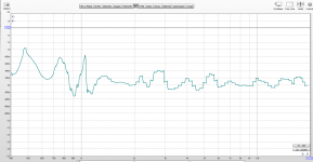
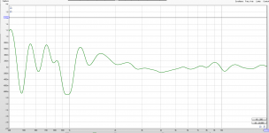
The solution to this as PB has alluded to with passive crossovers if to use asymmetrical electrical crossover slopes to add delay. In my practical implementation though I used a 4th order electrical slope on the tweeter and only the natural acoustic rolloff of the mids with a notch to get good results (I have attached a measured group delay plot to this post).
When implementing the same crossover digitally you can just implement the same slopes with IIR Linkwitz–Riley filters. Regardless you should just use a computer optimizer to properly constrain the problem and alter the parameters of the PEQs and filters you use. You also have the additional tool of pure delay to really tighten things up.
FIR processing would open up a lot of flexibility with the ability to alter phase and amplitude response of the drivers independently so the process could of optimizing the filter could become very mechanical, essentially been:
1) Flatten group delay and amplitude of drivers in pass band
2) Time align drivers with delay
3) Use phase corrected FIR crossover filter
I have plot the group delay of the SH-50 to illustrate what the final result should look like (basically flat) (yes took ages I ripped the data from the graphs).
1) constant group delay of summed output
2) flat summed amplitude response
3) limiting of HF power to tweeter (this means to crossover the mids as high as possible)
There are a number of constraints:
1) existing high frequency roll off of the mids (usually you push the mid as high as it will go)
2) fixed delay of the tweeter with respect to the mid due to path length distance
The solution to this as PB has alluded to with passive crossovers if to use asymmetrical electrical crossover slopes to add delay. In my practical implementation though I used a 4th order electrical slope on the tweeter and only the natural acoustic rolloff of the mids with a notch to get good results (I have attached a measured group delay plot to this post).
When implementing the same crossover digitally you can just implement the same slopes with IIR Linkwitz–Riley filters. Regardless you should just use a computer optimizer to properly constrain the problem and alter the parameters of the PEQs and filters you use. You also have the additional tool of pure delay to really tighten things up.
FIR processing would open up a lot of flexibility with the ability to alter phase and amplitude response of the drivers independently so the process could of optimizing the filter could become very mechanical, essentially been:
1) Flatten group delay and amplitude of drivers in pass band
2) Time align drivers with delay
3) Use phase corrected FIR crossover filter
I have plot the group delay of the SH-50 to illustrate what the final result should look like (basically flat) (yes took ages I ripped the data from the graphs).
Attachments
I'm getting out of my element here, but if memory serves, one of the issues you can run into is if the crossover order on the tweeter is too high.
moosebog.com is almost here! used to have the crossover schematic of the original Lambda unity horn. And if you looked at it, the tweeter xover was quite steep. Something like 3rd or 4th order.
With my xovers for my Unity horns in the last ten years or so, I use the solution proposed by LeCleach here: http://www.melaudia.net/zdoc/jml_crossovers_etf04.pdf
Here's a discussion that William and I had, about the original Unity xover, eleven years ago : Another Unity Horn
In a nutshell, it's quite easy to get flat response and well behaved phase response in a Unity horn. This is because the drive units are so close together; it's basically hard to screw it up. You can get quite good performance with as little as 3 or 4 passive components, total.
If you want to elevate things to the next level, the LeCleach paper explains one solution and I like it a lot.
Once "catch" with the LeCleach solution is that he includes a phase inversion. Whether this is taboo in a Unity horn is open to discussion.
I wish I was one of those people that could sit there and obsessively tweak a crossover until the loudspeaker can produce square waves. But, again, crossovers aren't my forte.
I will say that there's something truly eerie about the imaging of the SH50, and I personally think that the crossover has as much to do with it as the other elements.

The crossover is something else, and I get the impression that Danley has continued to refine it over the years. A real work of art.
When I rented those SH50s back in the day, I tried to buy them. They never replied to my email.
moosebog.com is almost here! used to have the crossover schematic of the original Lambda unity horn. And if you looked at it, the tweeter xover was quite steep. Something like 3rd or 4th order.
With my xovers for my Unity horns in the last ten years or so, I use the solution proposed by LeCleach here: http://www.melaudia.net/zdoc/jml_crossovers_etf04.pdf
Here's a discussion that William and I had, about the original Unity xover, eleven years ago : Another Unity Horn
In a nutshell, it's quite easy to get flat response and well behaved phase response in a Unity horn. This is because the drive units are so close together; it's basically hard to screw it up. You can get quite good performance with as little as 3 or 4 passive components, total.
If you want to elevate things to the next level, the LeCleach paper explains one solution and I like it a lot.
Once "catch" with the LeCleach solution is that he includes a phase inversion. Whether this is taboo in a Unity horn is open to discussion.
I wish I was one of those people that could sit there and obsessively tweak a crossover until the loudspeaker can produce square waves. But, again, crossovers aren't my forte.
I will say that there's something truly eerie about the imaging of the SH50, and I personally think that the crossover has as much to do with it as the other elements.
The crossover is something else, and I get the impression that Danley has continued to refine it over the years. A real work of art.
When I rented those SH50s back in the day, I tried to buy them. They never replied to my email.
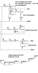
I believe this is the xover that used to be hosted on the Moosebog site.
That goes way back, to the days of The Bass List. In 2001 I was working for a failing dot com, and I would basically study patents to kill time, while I waited for all of us to get laid off.
The Unity patents were one of them, and got me started on this crazy journey.
I think John Sheerin was on the bass list also, and I believe he was the first person to ever build a DIY Unity horn.
....I will say that there's something truly eerie about the imaging of the SH50, and I personally think that the crossover has as much to do with it as the other elements.
The crossover is something else, and I get the impression that Danley has continued to refine it over the years. A real work of art...
Agreed 100%. I’ve had my SH50’s for years and they are still one of my favorite speakers of all time.
I have a SH64 crossover and driver set and can’t make sense of it from a strictly electrical standpoint but, that’s not my strong point either.
Barry.
When I rented those SH50s back in the day, I tried to buy them. They never replied to my email.
SH50I or SH50T Passive Install or Touring version $4,463
SH50IP or SH50TP Self-Powered Install or Touring $7,381
SH50-AT - Aqua tight - weatherized w/fiberglass finish $5,488
I have plot the group delay of the SH-50 to illustrate what the final result should look like (basically flat) (yes took ages I ripped the data from the graphs).
Attached Thumbnails
Hi kipman
I don't quite get it whether these group-delay graphs are from an actual group-deay measurement or if the were derived form the amplitude response.
My gut feeling is that they should actually look a little better. Or am I wrong ?
Regards
Charles
- Status
- This old topic is closed. If you want to reopen this topic, contact a moderator using the "Report Post" button.
- Home
- Loudspeakers
- Multi-Way
- The mysterious Danley crossover