conductive

http://www.youtube.com/watch?v=OQj9ueVFx5Q Time to eat an apple,no pun intended Jobs, RIP
Rob

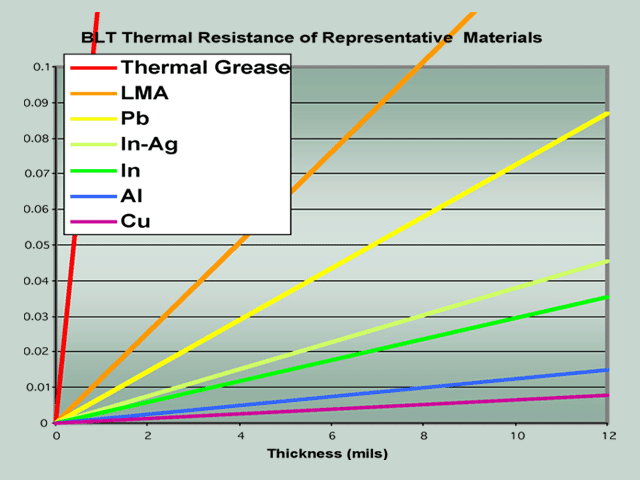
No Problem... THX I'll just make sure they cut the connection internally when they make them 🙂 Come to think of it, if they make sure the base of the FET is not electrically conductive I can just use silver foil, or have them machine them flat with silver bases, maybe to match silver heatsinks, ok I can use copper it is cheaper.. It seems that if the distance is zero, well it doesn't matter what you use, no thickness, direct mount. Cut the "wire", maybe there is a way to electrically BURN it off without hurting the FET, next thing to deal with, just have to make sure it can't re-weld itself or arc, FRY IT! And do it FAST! I have an excess of FET's to play with on this theory.. SwEET. This might do it, and make the power mesh FET's smaller at the same time!Indium is metal and electrically conductive.
You still need electrical isolation between FET & heat sink.
Patrick
http://www.youtube.com/watch?v=OQj9ueVFx5Q Time to eat an apple,no pun intended Jobs, RIP
Rob
Last edited:

Ke$ha - Crazy Kids ft. will.i.am - YouTube
Yep this video makes perfect sense, way early in the morning here, most everyone is sleeping, not me. I try to re-invent the world one day at a time. Kinda like James Belushi, coffee and beer and blood pressure pills, vitamins and water. I got a balancing act going on like you never seen, and ideas flow from the heavens... Can't stop now, were not "done", not by a long shot..... This one too.. http://www.youtube.com/watch?v=trQfLGqvotc If Janet ever fails me it's "Mary", if it's not mary, it's Ke$ha, I like her a lot... Dreams "can" come true, especially when you have the "Gefilter"... Just to remind you all, this is the "starter" amp for me in a sense, the future upgrades to this, well, like I said, they will re-invent the "radio" itself... Eat that Marconi RIP
Rob
Last edited:
An externally hosted image should be here but it was not working when we last tested it.
Re-living the past:, for at least the last 30 years I have been chasing this dream.... The "wonder" amp, the one that can drive anything with superior sound beaten by "nothing". It's only a 2 stage in "true" aleph tradition. Unbalanced and "pure"... Could I draw it, noooo, sure if I went back to skewel... No need. I gave the "wizard" my ideas and he had someone draw them. I was going to pay for it, but someone else did, and he gave the ultimate gift to us all, what he may have only dreampt of when making stuff like "super symmetry" and now he gave "us" the keys to the future. I don't know of anyone else in the history of audio world period, who would do that, they all wanted money, and you know money CANNOT buy happiness.... It stands true, the best things in life are "FREE", like the Mona Lisa that was drawn, sure the parts and engineering are gonna cost, but it's worth it in the end... I took the price tag down to like $5k and I still have room for improvement.... God bless Mr. Pass and the guy, whomever it was who drew the "future:" We should ALL give thanks for the Gefilter..
Rob
Last edited:
An externally hosted image should be here but it was not working when we last tested it.
I have decided to make my own heat sinks, to save money, let just say the entire world never, EVER, will ever have seen this technology... It's just plain crazy like "me", silver and copper (and not the kind that pulls you over with a beer in your hand... Siver wire all the way in audio paths.. Price just dropped to 3-4KRob
Ps: no water
Last edited:
heatsinks
An externally hosted image should be here but it was not working when we last tested it.I have decided to make my own heat sinks, to save money, let just say the entire world never, EVER, will ever have seen this technology... It's just plain crazy like "me", silver and copper (and not the kind that pulls you over with a beer in your hand... Siver wire all the way in audio paths.. Price just dropped to 3-4K, ok that changed, I do not want water, ease of use is AIR, copper heat sinks @280lbs a pop around $1k each. I think they might have been wrong with the software, will find out today.... I hope it was an error... They are huge but can handle 10kw each if I need it... FUTURE? I can still make them... price drops considerably...
Rob
Ps: no water
Last edited:
beer
Rob
I don't think so, nobody I know has a cheap pool like that... Just throw your Gefilter in it.. Only the beers look familiar...Hey Rob, do you know these guys?
Rob
I'm going to the casino, they have free beer and I usually make money there, it is on the way to my THE RAPIST... Ha!
ttyl
ttyl
I got it finally
Rob
The power strip in the pool, but for me it was real, I doubt that was even plugged in.. A pool like that is not grounded and I see no ground bus.. Joke HaHaHey Rob, do you know these guys?
Rob
I am surprised no one has steered you in this direction:
http://www.diyaudio.com/forums/pass-labs/43204-pass-monster.html
😀
http://www.diyaudio.com/forums/pass-labs/43204-pass-monster.html
😀
Yep. That's the thread I remembered. So painful. "Those who cannot remember the past are condemned to repeat it"-SantayanaI am surprised no one has steered you in this direction:
http://www.diyaudio.com/forums/pass-labs/43204-pass-monster.html
😀
 If, on the other hand, it could be rationally approached and executed, and made for $5K, that is low end Boutique. Price of entry level Pass Labs (or even First Watt territory). But...
Last edited:
nelson, the CCS is a little more complex than your previously published designs ?
The inputs are balanced already so a really stiff CCS seems an overkill
- so the question is:
Why the additional parts ?
The inputs are balanced already so a really stiff CCS seems an overkill
- so the question is:
Why the additional parts ?
Hundred ways to skin a cat. 🙂
Think thermal drift and local feedback around the 4N35.
There are of course other solutions.
Patrick
Think thermal drift and local feedback around the 4N35.
There are of course other solutions.
Patrick
The CCS that you have specified tells us that this is a single ended amplifier with a bias of 5A.a more doable version could be: 14 IRFP240 gainstage Devices and 14 IRFP240 CCS devices @0.36A pr device for a total of around 5A bias and +/-85VDC rails. thats about 400W class A @8ohm. total consumtion of about 2KW for 2ch. still crazy amount of power.
The maximum peak output is also the maximum ClassA output and is 5Apk.
The maximum power into 8ohms will be Ipk²R/2 = 5*5*8/2 = 100W
Is it not true that when Q7 ..... Q21 are not conducting, R19....R61 will have no voltage drop, and the top current source will deliver 2x the bias current ?
Patrick
Patrick
Last edited:
The specs of my dream amp: While no elekthroniks guy, I did ask for several things, 1KW/ch @ 8 ohms, 2KW/ch@4ohms, Isotops, Using Mu Follower design, and retain the aleph tradition of single ended unbalanced class "A". Whether this spec holds true I can't say, can I build it, No Doubt!
Rob
Rob
Hundred ways to skin a cat. 🙂
Think thermal drift and local feedback around the 4N35.
There are of course other solutions.
Patrick[/
Thanks I understand how the local feedback works.
So the reason this was put in place is to counteract thermal drift in the Ccs ?
drift
Hundred ways to skin a cat. 🙂
Think thermal drift and local feedback around the 4N35.
There are of course other solutions.
Patrick[/
Thanks I understand how the local feedback works.
So the reason this was put in place is to counteract thermal drift in the Ccs ?
I think that is true and I think Mr. Pass addressed this earlier.
Rob
The CCS that you have specified tells us that this is a single ended amplifier with a bias of 5A. The maximum peak output is also the maximum ClassA output and is 5Apk. The maximum power into 8ohms will be Ipk²R/2 = 5*5*8/2 = 100W
If you are referring to the schematic in post #1, the nominal bias current
is 8 amps, and it will deliver twice that peak, as it is not a CCS.
This gives about 2KW peak into 8 ohms.
😎
- Home
- Amplifiers
- Pass Labs
- The Mu Monster
