@ tiefbassuebertr
This "might" be the guy ?
United States Patent Application 20090309659
Published Applications Database Search Results: <SRCH> in <BANR>.
You could try & contact him via those addresses !
This "might" be the guy ?
United States Patent Application 20090309659
Published Applications Database Search Results: <SRCH> in <BANR>.
Micro-Coaxial Lines for Active Hybrid-Monolithic Circuits," N. Ehsan, E. Cullens, K. Vanhille, D. Frey, S. Rondineau, R. Actis, S. Jessup, R. Lender Jr., A. Immorlica, D. Nair, D. Filipovic', Z. Popovic', IEEE International Microwave Symposium Digest, 2009, pp. 465-468, Boston, MA, June 2009
University of Colorado - Microwave and RF Research Group - Publications
You could try & contact him via those addresses !
"There is no evidence anywhere that this is true. "
That you are aware of.
I would have to think that the local feedback, accomplished with no extra parts, would have to improve the linearity.
Do you have any measurements to back up your doubt?
Could it be improved on, given a different topology and more parts? Maybe, maybe not. Tests and measurements might help, but will it sound any better?
Active current sources for loads in the front end improve the open loop gain, and while that reduces the distortion measurement, it may sound worse. Is this progress? Is this worth increasing the complexity and parts count?
From my perspective good amplifier design is about maximising forward path linearity while maximising forward path gain, and, simultaneously, minimising forward path poles.
Folded (or complementary) cascode arrangements like those of Borbely and Lender are effectively single gain-stage designs which do not maximise forward path gain or improve forward path linearity anywhere near enough to justify their use.
The best compromise is obtained by using a two stage design where local feedback can be used to enhance forward path linearity without excessively reducing the forward path gain necessary for adequate loop gain when major loop feedback is applied.
Moreover, the two gain stage design generates two dominant poles in the forward path that can be split by means of minor loop feedback (Miller compensation, TPC, "TMC") about the second stage to stablise the major feedback loop.
".of course active current sources add to distortion. "
I have actually seen measurements showing the distortion decreasing by an order of magnitude, yet listening tends to show the opposite.
"Folded (or complementary) cascode arrangements like those of Borbely and Lender are effectively single gain-stage designs"
Are we talking about the same topology?
I think not.
Last edited:
Are we talking about the same topology?
I think not.
Which topology are you talking about then?
The thread is about the Lender circuit, isn't it?🙄

Yes; Lender's circuit is, in fact, a single gain stage design; not good.
If you're obliged-for some unfathomable reason-to use a single stage folded cascode arrangement, then Shinichi Kamijo's topology is recommended:
http://www.ne.jp/asahi/evo/amp/index.htm
If you're obliged-for some unfathomable reason-to use a single stage folded cascode arrangement, then Shinichi Kamijo's topology is recommended:
http://www.ne.jp/asahi/evo/amp/index.htm
Last edited:
URL is death. but this link goes open:Thank you for this advices. here the right link:
1) 404 | University of Essex
If don't goes open please copy this in the URL address field and add the correct characters at the beginning and at the end as a substitute for the wrong
2) http_www_essex.ac.uk/csee/research/audio_lab/malcolmspubdocs/J10%20Enhanced%20cascode_pdf
then the URL will no longer be mutilated further through this forum
https://web.archive.org/web/2013012..._lab/malcolmspubdocs/J10 Enhanced cascode.pdf
Last edited:
I don't find, what you mean. Also not underYes; Lender's circuit is, in fact, a single gain stage design; not good.
If you're obliged-for some unfathomable reason-to use a single stage folded cascode arrangement, then Shinichi Kamijo's topology is recommended:
http://www.ne.jp/asahi/evo/amp/index.htm
https://www.ne.jp/asahi/evo/amp/guide.htm
Attachments
URL is dead, I have upload the pdf in my previous post."by the thread title you'd be better off pursuing cascodes:
REDUCTION OF TRANSISTOR SLOPE DISTORTION IN LARGE SIGNAL AMPLIFIERS, M.O.J. Hawksford, JAES, vol.36, no.4, pp.213-222, April 1988
http://www.essex.ac.uk/csee/research... cascode.pdf "
This is the VAS technique I was refering to in my earlier post on this thread.
Using the simple standard current amplifier topology front end, but modding the VAS stage to use Hawksfords technique, I consistently get THD (simmed) below 500ppb. Between the VAS and the load, I'm using a diamond buffer. Hawksfords VAS is really amazing in my view. This weekend, I plan to mod my power current power amp VAS to Hawksford (I was supposed to do it a few weeks ago, but have not had time).
Not sure if they are related other than the name, have you looked at Hugh’s Aksa-Lender preamp? Which makes a pretty good high voltage swing preamp.
https://www.diyaudio.com/community/threads/aksas-lender-preamp-with-40vpp-output.314563/
https://www.diyaudio.com/community/threads/aksas-lender-preamp-with-40vpp-output.314563/
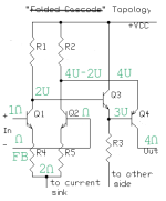
To help folks to understand the specifics of these arrangements better, I supplied
the Lender-Borbely input circuit with the signal flow (digits) and the signal polarities
(U, and inverted). That will explain that there is no cascode action whatsoever,
and the Miller effect is reduced only due to the Neg. FB signal' amplitude reduction.
Without Neg. FB the Miller effect at the input FET will be in full bloom.
In fact, we create the same problem for the second FET in the LTP, which receives
the FB signal.
The correct assessment of this arrangement was given in:
www.diyaudio.com/community/threads/power-amp-driver-block-topology.2309
posts ##2, 6, 16.
↴
Attachments
Last edited:
In comparison, JC3 input (schematic is taken from LtE in the "Wireless world" mag.)
not only compensates the gate associated input capacitance to zero, but can
overcompensate that C when the bootstrapping action will turn into the Positive FB
due to excessive first transistor gain ⩾ ½Gm×220Ω -if it will be more than ≈1.
That compensation is important since we employed the series 10KΩ resistor at
the input in the shunt/parallel Neg. FB arrangement - to eliminate/reduce the
significant value of the input τ=Rin(10K)×Cin.
And in this circuit there is also no cascode action whatsoever, just bootstrapping -
imposing the proper signal polarity on the input FET' drain for the desired effect.
Consider yourself warned.☝ ☺
Attachments

It will be helpful to some members here to add an useful observation from JCarr on the subject:
Lars: Regarding the JC3 topology, you can add degenerator resistors to the sources/emittors of the input devices, and adjust these together with the collector/drain resistor values so that you can vary the voltage gain on the base of the VAS. My own experience is that no gain works and sounds the best, but OTOH, my experiences are my own and not necessarily relevant to anyone else.
regards, jonathan carr
regards, jonathan carr
Very interesting.
Just one comment, from having looked at many power amps from Borbely I can say that he usually cascodes the input quad. Sometimes he uses a fixed cascode, sometimes a Baxandall (common base/gate referenced to emitters/sources, not fixed).
I like the Slone dual mirror, I know it's not a straightforward thing (as shown in the book it has undefined bias, unbounded VAS drive - no current limitation at all). I am working on my solution in the sim, and I want to give it a try
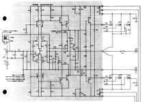
Hafler-XL280 (probably designed by Mr. Borbely)
At first glance you might think the schematics are wrong (look at the references for cascode bases).
What he's doing is very clever: the driven cascode is used only for the P-channel jfet, the 2SJ72. This arrangement mitigates the reverse transfer capacitance, bootstrapping it to a good degree. The P-channel is much more troublesome than N in regards to capacitances and high frequency, but with this bootstrap the whole input stage will behave more symmetrically at HF.
Attachments

To the post-56 current mirror + VAS interface unpredictability:
This problem was discussed here many years ago (in 25 years of this forum existence)
with inclusion of FB resistor from the mirror output collector to the combined bases.
Another FB solution was presented by JLH in EW-1985 (attached):
This problem was discussed here many years ago (in 25 years of this forum existence)
with inclusion of FB resistor from the mirror output collector to the combined bases.
Another FB solution was presented by JLH in EW-1985 (attached):
Attachments
I like fully-complementary topologies, but I see why they have disappeared from the mainstream. Amplifying the difference in offset voltages between the complementary halves precludes high open-loop gain.
Ed
Ed
- Home
- Amplifiers
- Solid State
- The most linear stage for large voltage swings - Lender's Circuit