I want to build The Optimized Morgan Jones Amplifier but I have question about output cap beacuse I want to use film instead lytic: the schematic uses 470uF 350V, really is necessary so big or I can use a small film cap like 27uf or 10uF or less?
An externally hosted image should be here but it was not working when we last tested it.
Too small a capacitor and you will have bass rolloff. Figure input impedance of headphones and calculate the rolloff with selected capacitor.
Jam
Jam
First-order continuous-time implementation
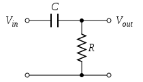
Figure 1: A passive, analog, first-order high-pass filter, realized by an RC circuit
The simple first-order electronic high-pass filter shown in Figure 1 is implemented by placing an input voltage across the series combination of a capacitor and a resistor and using the voltage across the resistor as an output. The product of the resistance and capacitance (R×C) is the time constant (τ); it is inversely proportional to the cutoff frequency fc, that is,
where fc is in hertz, τ is in seconds, R is in ohms, and C is in farads.
Attachments
Last edited:
I calculate 265uF for a load of 300 ohms (HD600), do you know if I can substitute the cathode resistor/capacitor with a 1.9-2.0-2.1V 20mA LED?
Last edited:
I once built a version of this amplifier - using a triode-connected EF86 on the front end, but with the same 6922 back-end - I did use electrolytics on the output, bypassed with Dayton polypropolenes. Really, it sounded quite good and certainly changed my mind about the "sound of electrolytics". If I remember correctly, I just used some Panasonics from Digikey.
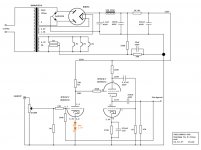
Thanks Stixx, I'm currently using the Valve Wizard mu-follower, I'm satisfied but I received advice that my Senhs HD600 plays better with an output impedance of 120 ohms, the mu-follower I'm using have an output impedance of 257 ohms so to big also I know HD600 have an output impedance of 300 ohms so the question is: wich value of SE output line transformer have I to install?, mu-follower schematic:
Last edited:
I once built a version of this amplifier - using a triode-connected EF86 on the front end, but with the same 6922 back-end - I did use electrolytics on the output, bypassed with Dayton polypropolenes. Really, it sounded quite good and certainly changed my mind about the "sound of electrolytics". If I remember correctly, I just used some Panasonics from Digikey.
I eard people used EF86 for MM phono preamp with great success.
A weakness of that MJ circuit is that it uses electrolytics to set the LF rolloffs. This is the most likely scenario to make electrolytic distortion a problem. Add an input coupling cap to set the LF rolloff, then ensure that the electrolytics are big enough to have very little signal voltage across them.
After the pot would be better, between the slider and R1. The value would depend on how big you are prepared to go with the other electrolytics. The basic idea is that the input LF rolloff, set by the cap and R1, is higher in frequency (by a factor of 2-5?) than the output rolloff, set by C4 and your headphone resistance. Also the cathode decouplers.
You also want the White follower to work properly, so the input cap should be less than C2.
You also want the White follower to work properly, so the input cap should be less than C2.
CR first-order high pass filter. Use a calculator, or simply build the circuit as it is. Modding a circuit may require understanding and arithmetic.
First-order continuous-time implementation
Figure 1: A passive, analog, first-order high-pass filter, realized by an RC circuit
The simple first-order electronic high-pass filter shown in Figure 1 is implemented by placing an input voltage across the series combination of a capacitor and a resistor and using the voltage across the resistor as an output. The product of the resistance and capacitance (R×C) is the time constant (τ); it is inversely proportional to the cutoff frequency fc, that is,
where fc is in hertz, τ is in seconds, R is in ohms, and C is in farads.
The natural frequency is proportional to 1/(RC) which is radians/second. You need a factor of 2 pi to get this in units of Hertz. In other words, fc = 1/(2 pi RC).
The natural frequency is proportional to 1/(RC) which is radians/second. You need a factor of 2 pi to get this in units of Hertz. In other words, fc = 1/(2 pi RC).
Using 220nF
fc= 1/(2 pi X 1000000 ohms X 0.00000022 farads) = 1/1.38 = 0.72Hz😕
For 300 ohm headphones, a 47µ film capacitor on the output does the job. Fc(-3dB)=11.3 Hz
Last edited:
Here you go... 😉
But when you want my opinion you'd better spend the money on output transformers than trying to pass the audio signal through humongous film capacitors.
There is something I don't like about that schematic. You are using fixed (LED) bias without a CCS load and with a 1M grid resistor. You risk instability.
For 300 ohm headphones, a 47µ film capacitor on the output does the job. Fc(-3dB)=11.3 Hz
47uF film cap as output gives me 112.88Hz not 11.3Hz
- Home
- Amplifiers
- Tubes / Valves
- The Morgan Jones mini tube headphone Amplifier