To appreciate my distaste for taps, you would need to know how I've made a living for the past 26 years...
The tread cutting screws I'm referring to cut threads that are as good as the threads cut by a tap:

They are harder than standard machine screws (to withstand the stress of thread cutting), are removable and will torque down as well as any machine screw.
...with little rectangles.
The tread cutting screws I'm referring to cut threads that are as good as the threads cut by a tap:
They are harder than standard machine screws (to withstand the stress of thread cutting), are removable and will torque down as well as any machine screw.
All options would work , threaded /tapped could most likely be torqued harder. I suppose this falls into the same category as people that paint their speaker cones...
...with little rectangles.
Ahh , those are the "good" self- tappers. You could use those as the actual tap ! Have you ever snapped them off in a hole ?
OS
OS
I haven't used those particular ones yet, so I can't actually vouch for their quality. I do have some 4-40 and 6-32 on order to try. I'll report back.
Yes, using the screws in the same way as you would use a tap is the best way. Not a good idea to drive these straight in with a drill, like you are building a deck. Use lube (alcohol) and a screw driver. Make sure you have the exact right size drill bit to make the correct sized hole - #41 drill for 4-40 screws, for example.
Yes, using the screws in the same way as you would use a tap is the best way. Not a good idea to drive these straight in with a drill, like you are building a deck. Use lube (alcohol) and a screw driver. Make sure you have the exact right size drill bit to make the correct sized hole - #41 drill for 4-40 screws, for example.
I haven't used those particular ones yet, so I can't actually vouch for their quality. I do have some 4-40 and 6-32 on order to try. I'll report back.
Yes, using the screws in the same way as you would use a tap is the best way. Not a good idea to drive these straight in with a drill, like you are building a deck. Use lube (alcohol) and a screw driver. Make sure you have the exact right size drill bit to make the correct sized hole - #41 drill for 4-40 screws, for example.
That's why I never break the taps , lube and the proper sized drill for the specific tap
The self tappers would be driven like a real tap (2 turns in - back out 1)
Alcohol is better as a lube ?? 😀 I always use 3m oil. As long as you cancel out AL2/ O3 formation either would work ?
OS
Last edited:
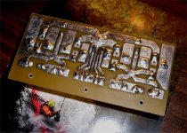
Here's a six transistor OP stage arrangement of mine. It offers an overall pcb size of 85mm x 111mm when used with, for example, my modded FC-100 (additions plus VI limiter) pcb layout. Designed to comfortably fit six into a 2U rack.
Brian.
Brian.
Attachments
Hi OS,
I think you may be at the stage where you really need to determine who your potential market is. Look at the stuff sold on ebay for high volume, low price and profitable versus DIYAudio specific options (low volume, higher cost, any profit?). Another marketing model worth looking at are the SiliconChip amps, 10's of thousands or possible 100's of thousands have been sold over the years. As pointed out, the SC PCBs are relatively large possibly to make it easier for construction for first timers.
You might also want to talk to Hugh as he has been though all this before and has changed the way he does things significantly depending on the market he is aiming at.
On economics, a couple of good quality taps can cost more than the output devices on the amp. Those self tapping screws look a good option. Personally, I would never use self tappers or anything non-metric, but... I am not someone you would be selling too so my opinions don't count.
In Australia, I think a lot of our PCB designs have been based on the availability of high quality, low cost heatsinks from Conrad. I know all the Aspen amps until recently, Greg Ball's amps and most of the SiliconChip amps use these heatsinks. If you are after a world-wide market you'll have to account for a lot more options of hardware availability.
regards and good luck.
Thanks Greg , I have studied the Aspen Amps business model as well as Silicon chip , Aussieamps , Ampslab , and the various Ebay offerings.
" Knowing your market "... exactly why I am soliciting feedback from fellow members. I never bought kits from others as the pads de-laminated , they were either too big or too small , DIY is truly DIY !! I will talk to Hugh again as I know he is the "expert". My own sourcing experiences and discussions with international DIY'ers have given me a lot of insight on what just may work.
Mega profit is not the goal - just a little to support R and D and my beloved hobby. 🙂
OS
Here's a six transistor OP stage arrangement of mine. It offers an overall pcb size of 85mm x 111mm when used with, for example, my modded FC-100 (additions plus VI limiter) pcb layout. Designed to comfortably fit six into a 2U rack.
Brian.
Boy , you are using every square mm of that bracket !! 😱 Awesome !!
OS
just a little to support R and D and my beloved hobby. 🙂
OS
You might be saying goodbye to the 'beloved' part if you pursue this. Be prepared to be hounded to death regarding the silliest things - shipping first and foremost.
You might be saying goodbye to the 'beloved' part if you pursue this. Be prepared to be hounded to death regarding the silliest things - shipping first and foremost.
Yes , the old saying that friends and business can be incompatible , sort of like religion and politics. Even if you are perfect , you will encounter somebody that is "unplease-able" . 🙄
OS
Boy , you are using every square mm of that bracket !! 😱 Awesome !!
OS
Hi OS,
Thank you.
Brian.
With your heatsinks, "fishing" the screws through the fins would be no problem , but not everybody has YOUR heatsinks. 😀 What if the fins were spaced different ?? A "tappin'" you would have to do !
OS
My main concern with some of the examples is to Avoid creating a miniature oven underneath the circuit board (heat pooling).
As for mounting onto heatsinks, it would usually work fine if the output devices were soldered after mounting them on the heatsinks. That might not be as pretty as using a bracket, but either solution happens to work.
Yes, a heat spreader bracket might be prettier and easier and promotable, which is good for marketing--one possible way to choose amongst the several well working options available.
I'm fine with whatever option you choose, except for heat pooling. 🙂
You might be saying goodbye to the 'beloved' part if you pursue this. Be prepared to be hounded to death regarding the silliest things - shipping first and foremost.
"Your option to paying shipping is to pick up the item from our factory location at the south pole." 🙂
Yes , the old saying that friends and business can be incompatible , sort of like religion and politics. Even if you are perfect , you will encounter somebody that is "unplease-able" . 🙄
OS
Solution: "P.I.A. Fee"
This is commonly used in support as a pricing category that allows those who need extra support to pay for it. There's nothing wrong with charging proportionately to the difficulty in rendering services.
Summary:
Well, just don't give it away.
P. I .(t) A. !!!!
PIA fee ... huh ! 🙂
No sleep is more like it. Selling all the previous mongrels (4 PB250's/AX's) , building the Nikko mongrel out of new miracle FR-4 (teflon) , and designing the new cool mongrel kit. PIA , but I like it !
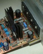
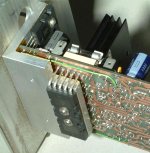
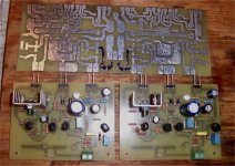
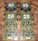
The Nikko big PS board is done , the weird FR-4 is crazy stuff ... IT WILL NOT BURN. (Below 1 and 2 ) are photo's of this "stuff" , it feels slippery like a frying pan and the iron will not de-laminate pads or deform it at ALL !!
I chose the previous example 2 for a board layout (angle bracket mounting) and am working on the final (AX120 kit). I have to take care of all this shipping first , then I will show and tell. The AX120 will be the same as my nikko but NOT modular. It will have the same specs as my PB120/AX combo (120/240w - 8/4R , 5hz-100khz BW , .0003% thd @ 1k/60w). Cap multipliers and dual power supply/ground capable ... same as my modular creations.
Off to the post office ...
OS
PIA fee ... huh ! 🙂
No sleep is more like it. Selling all the previous mongrels (4 PB250's/AX's) , building the Nikko mongrel out of new miracle FR-4 (teflon) , and designing the new cool mongrel kit. PIA , but I like it !
The Nikko big PS board is done , the weird FR-4 is crazy stuff ... IT WILL NOT BURN. (Below 1 and 2 ) are photo's of this "stuff" , it feels slippery like a frying pan and the iron will not de-laminate pads or deform it at ALL !!
I chose the previous example 2 for a board layout (angle bracket mounting) and am working on the final (AX120 kit). I have to take care of all this shipping first , then I will show and tell. The AX120 will be the same as my nikko but NOT modular. It will have the same specs as my PB120/AX combo (120/240w - 8/4R , 5hz-100khz BW , .0003% thd @ 1k/60w). Cap multipliers and dual power supply/ground capable ... same as my modular creations.
Off to the post office ...
OS
Attachments
The most important thing is to have a good quality heat transfer from transistor to heatsink
You dont need a very high force and dont need a special steel screw.
It is more important to have a pair of very flat surface and make sure there is no burr around the hole.
A tapped hole with a machine screw is the best way.
When you torke the screw and you can feel how much pressure you get
With a self tapping screw it is difficult to set at the correct pressure the screw itself need a torke to make or cut threads.
With a self tapping screw it is difficult to set at the correct pressure the screw itself need a torke to make or cut threads.
Procedure:
1. Buy screws, drill bit.
2. Drill hole with drill bit.
3. Drive screw, using lube, all the way in.
4. Remove screw.
5. Deburr edge, clean hole.
If this sounds like tapping, you are getting it.
Just about finished with my "PIA". Capt. Grogg (member) helped me , he will get the PB60X2 - BX (needs input caps) like my old faithful barn amp (below 1). I still have the 2 big 250W amps(below 2) , they are thumpless (turnon) , noiseless , and virtually distortionless ... my best , most reliable to date - PM me for more info. I want smaller amps (nikko)/w - smaller speakers and DIY sub/amp combo. No big "lanky" monster amps allowed. 🙁
OS
OS
Attachments
The most important thing is to have a good quality heat transfer from transistor to heatsink
You dont need a very high force and dont need a special steel screw.
It is more important to have a pair of very flat surface and make sure there is no burr around the hole.
A tapped hole with a machine screw is the best way.
When you torke the screw and you can feel how much pressure you get
With a self tapping screw it is difficult to set at the correct pressure the screw itself need a torke to make or cut threads.
I am working on that , even with a 100 X 150mm (75 X150mm is also on the table) angle mount style layout with 2 pair OP's , the 2 drivers and the VBE ... one could mount all 7 devices under the board with larger holes above to accommodate the hardware/screwdriver. If I designed for the clearance of the larger hole but also allowed for the smaller hole , one would have the choice of either thermal option. The PB250's are mounted this way and they are easy to work on , even the Vbe ... which is beneath a 10mm hole.
I , for one would never accept the angle mount. I have tried it and direct mounting is far superior. I will make 1 of my new AX120 with NJW21193/4 pairs AND mount it this way to show the universality of my new design. (250W/4R sub amp).
OS
Last edited:
Time to build some more... (m.o.a...n ? )
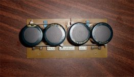
Next is the CRC higher voltage supply (below 1) that Danielwritesback thought I was going to power the Output stage with. 😀 It's star return will go to the center of the main PS's star. Real simple , but effective.
I simulated (haven't done that in a while - too busy with the real thing 😀) the worst case 2R load of a NJW21193/4 OPS. The driver currents would be no more than 600mA - both channels combined (below 2). So , 1.5A diodes and the 8 small caps in the HV supply board will be more than adequate. My added CRC will smooth the current pulses from the drivers enough to run the +/- cap multipliers. It may be noted that I AM running my drivers from the HV supply. This will allow my OPS to swing FULL rail to rail (+/-.6V) , clipping way before the drivers/voltage stages do.
Of course , the Voltage stage will have it own ground return to main star to avoid current pulses from any other source. These considerations may seen "Anal" , but it seems a few Japenese audio engineers agree. 😀
OS
Attachments
- Home
- Amplifiers
- Solid State
- The MONGREL (supersym II)