The original Aksa Lender was designed to drive a 5k ohm load and 47uF was fine. After we started on the M2X Melbourne, I think the 600ohm load came up later as a post by someone. The published value of the Edcor impedance in the M2 manual was much higher.
In any case, I have used 47uF to drive 250ohm headphones before and it sounds pretty good.
Characteristic high pass frequency is 1/(2pi R C). 47uF and 600ohms gives about 5Hz and if we go two octaves higher to make sure we are well beyond the corner, we are at 20Hz, the low limit of audible sound frequency. Phase deviations below 100Hz are not really audible due to the long wavelengths and how they interact with the room. So 47uF could actually work quite well still.
Last edited:
If 47uF is needlessly oversized, reduce it. Save people some money when buying components, and give them the opportunity to learn for themselves whether they hear any difference between 15uF (?) on Melbourne and 220uF on the other daughter cards.
edit- You might also choose to think about the low frequency roll off created by the 10uF AC coupling capacitor called "C2" on Nelson Pass's Official M2 Schematic. It occurs at some frequency "f_nelson_c2" that you can calculate or simulate. Do you want the roll off frequency created by the Melbourne output cap, to be above, below, or equal to f_nelson_c2? In your opinion, should one of these two LF roll off corners "dominate" the other? If so, which? Why?
edit- You might also choose to think about the low frequency roll off created by the 10uF AC coupling capacitor called "C2" on Nelson Pass's Official M2 Schematic. It occurs at some frequency "f_nelson_c2" that you can calculate or simulate. Do you want the roll off frequency created by the Melbourne output cap, to be above, below, or equal to f_nelson_c2? In your opinion, should one of these two LF roll off corners "dominate" the other? If so, which? Why?
Last edited:
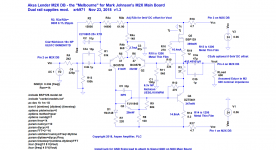
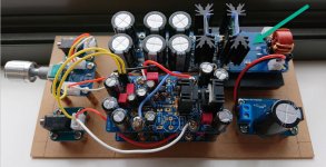
Motherboard for the Melbourne to run as stand-alone preamp/HPA
The YARRA Preamplifier/HPA for Melbourne DB Group Buy
The YARRA Preamplifier/HPA for Melbourne DB Group Buy
X,
Been looking up parts to build it up as a HPA as per the HPA schematic on the Yarra thread. I just wanted to check a few things ....
1) On the input which parts should be removed for DC coupling (I won't be building with the Yarra board) - should all the crossed out components on the input be omitted? (R101, R102, C 101, C102, C103). Or is it just C102 and C103 which should be omitted?
2) Which resistors need to be carbon/thin film/a specific type? From what I gather R119 - carbon/thin film, R104, R106, R114 & R116 thin film 0.1%, any others? (the schematic which is in blue adds R14 & R15 as thin film.. R14 is R125 in the production schematic but I can't find R15 on the diagram)
Will any need to be higher power resistors or will the usual 1/4W all round be fine?
3) Just saw the melbourne X american beauty...any benefits? If I'm building the melbournes with the revised resistors/mosfet as per the HPA, would the american beauty output stage in the schematic good to go as drawn?(The Melbourne Class A Headphone Amp and Pre-amp)
Attachments

Last edited:
YOB,
If using Melbourne board standalone, leave all the input stage parts - the input needs a cap coupled input. The drawing is to show that you can do it on the Yarra.
Change the others as shown in the drawing above. You can still use 1/4w axial resistors on everything. Power dissipated is i^2 x R. So 0.1A squared x 10ohms is 100mW. Not too much for 250mW rated part.
Only the feedback resistor needs to be CF.

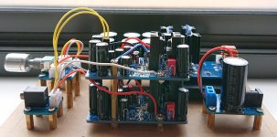
Nice work yourownbuzz - like the stacked assembly! 🙂
Regarding V121, 122 - what heat-sinks are you using now and what are their dimensions?
Regarding V121, 122 - what heat-sinks are you using now and what are their dimensions?
Looks great YOB! Nice looking and very tidy. Will you be putting this in a real case at some point?
Where did you get those little boards for the 3.5mm Switchcraft jacks? I don’t recall that being part of the SHPA board-set?
How does it sound?

Where did you get those little boards for the 3.5mm Switchcraft jacks? I don’t recall that being part of the SHPA board-set?
How does it sound?
zman: Using the Fischer SK95-25-SA-220 - someone posted it as the part number that goes with the board. or maybe it was in the BOM.
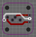
x: I spent an inordinate amount of time on easyeda making small breakout boards for the volume pot, the switchcraft jacks and the DC socket. I ordered a bunch of the jacks way back when for the PCA build. The jack pcbs were $5 for 20 from jlcpcb. can share the gerbers when I get back to the computer if anyone's interested.
A case would be nice but no immediate plans - in the future perhaps.
YOB,
Your boards look great, they even match the style of the original SHPA. I think JP provided a separate potentiometer/volume knob sub-board with the SHPA that looks jut like that. Did you make a new one? Cool that you learned easyEDA.
Regards,
X
Your boards look great, they even match the style of the original SHPA. I think JP provided a separate potentiometer/volume knob sub-board with the SHPA that looks jut like that. Did you make a new one? Cool that you learned easyEDA.
Regards,
X
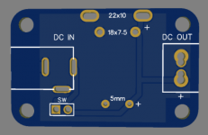
Yep I made another volume board.. figured it will come in handy for other projects as well. Here's the easyEDA pictures of the 3 boards and gerbers for them.
I don't think the DC in board is that interesting, its just 5.5 2.5 jack to a terminal block / 0.1" spaced holes, with space for an electro and film/1206 (on the underside) smoothing caps, and connection point for a switch. One thing I forgot was to add an LED power indicator...not that its necessary for it to function.
I don't think the DC in board is that interesting, its just 5.5 2.5 jack to a terminal block / 0.1" spaced holes, with space for an electro and film/1206 (on the underside) smoothing caps, and connection point for a switch. One thing I forgot was to add an LED power indicator...not that its necessary for it to function.
Attachments

Hi Redjr,
That is part of the DC coupled Simple Headphone Amplifier PCB set which is now sold out. However, I have that PSU board all by itself if you are interested in getting it.
Simple High Performance DC Coupled Class A HPA with sub PPM THD
That is part of the DC coupled Simple Headphone Amplifier PCB set which is now sold out. However, I have that PSU board all by itself if you are interested in getting it.
Simple High Performance DC Coupled Class A HPA with sub PPM THD
Last edited:
Spice Simulation
I'm trying to simulate the circuit in LTspice but it won't even bias. I think I have the component values correct as per the schematic in post #1, and I found the models for the various actives on the internet. Is there something I'm failing to include in the model (attached) besides the base schematic? Or did I miss something obvious?
Additionally, the connection of the 8.2R resistor differs in your LTspice schematic and the later JPS64 schematic (it's labeled R14 and R125, respectively, in the two original schematics) - which is correct?
Here is the schematic on LTspice
I'm trying to simulate the circuit in LTspice but it won't even bias. I think I have the component values correct as per the schematic in post #1, and I found the models for the various actives on the internet. Is there something I'm failing to include in the model (attached) besides the base schematic? Or did I miss something obvious?
Additionally, the connection of the 8.2R resistor differs in your LTspice schematic and the later JPS64 schematic (it's labeled R14 and R125, respectively, in the two original schematics) - which is correct?
Attachments
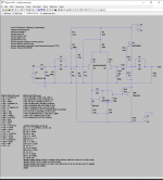
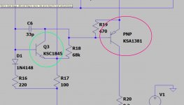
The error is in the definition of the labelled `PNP' - it should show Q4.
Thanks! This appears to be an artifact of my own debugging attempts. After making this change, it still didn't work.* However, I found a different "DN2540" model directly from Microchip - and it now appears to be working!
*I did subsequently try Q4 labeled both ways, and it works both ways - I'm not what functional change the labeling makes, but for future debugging, I don't think it caused Q4 to completely fail to function.
Attachments
Last edited:
I deleted all of the ".model" and ".subckt" operators and just right click edited the PNP and NMOS to the stock models.
Set an input voltage greater than 0, corrected the FFT command (V(OUT) not (V(OUTPUT)) and it seems to run fine.
*(I say stock models, but ages ago I upgraded my LTSpice with a so-called 'mega pack' of models so I can't say for sure if those models are in the stock standard install of LT).
Set an input voltage greater than 0, corrected the FFT command (V(OUT) not (V(OUTPUT)) and it seems to run fine.
*(I say stock models, but ages ago I upgraded my LTSpice with a so-called 'mega pack' of models so I can't say for sure if those models are in the stock standard install of LT).
Attachments
Last edited:
Thanks - my bare-bones installation doesn’t have the necessary models. With the new model I found this morning, the sim works great.
The V(OUT) is a copy-paste error from my other window - thanks for catching that.
The V(OUT) is a copy-paste error from my other window - thanks for catching that.
- Home
- Amplifiers
- Headphone Systems
- The Melbourne Class A Headphone Amp and Pre-amp