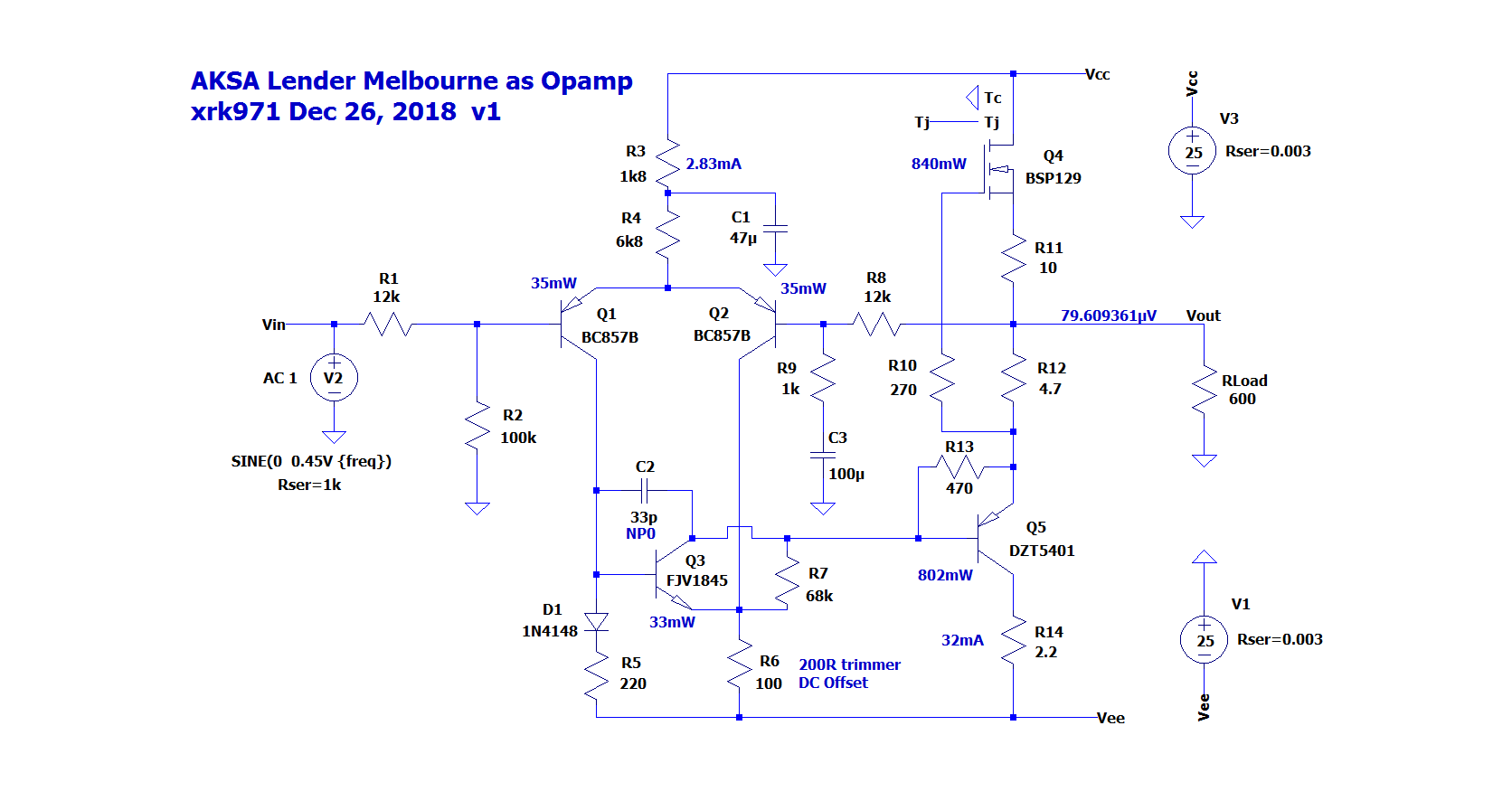
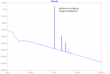
I was trying to see how the Melbourne could be made into an Opamp. A 5 active opamp with nice sonic performance is kind of cool.
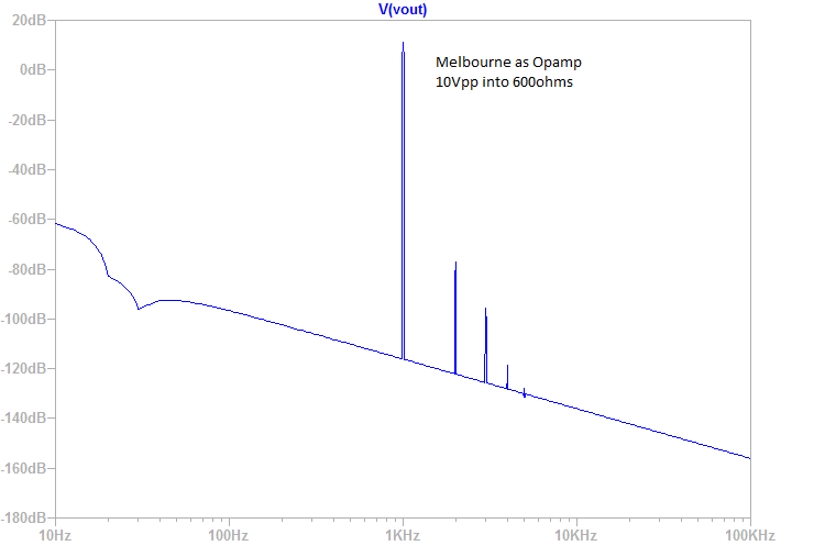
10Vpp into 600ohms:
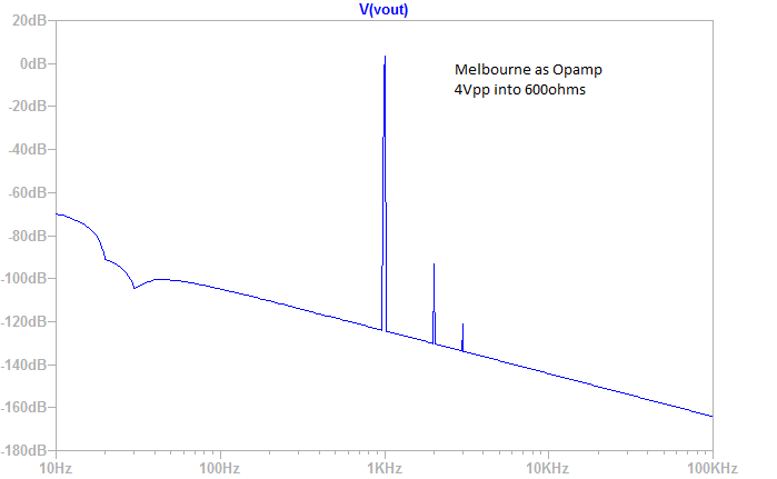
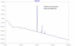
Here is 4Vpp into 600ohms:
10Vpp into 600ohms:
Code:
10Vpp into 600ohms
Harmonic	Frequency	 Fourier 	Normalized	 Phase  	Normalized
 Number 	  [Hz]   	Component	 Component	[degree]	Phase [deg]
    1   	1.000e+03	5.148e+00	1.000e+00	    0.07°	    0.00°
    2   	2.000e+03	2.004e-04	3.892e-05	   92.48°	   92.41°
    3   	3.000e+03	2.127e-05	4.132e-06	    1.90°	    1.83°
    4   	4.000e+03	2.736e-06	5.314e-07	 -144.17°	 -144.24°
    5   	5.000e+03	1.918e-06	3.727e-07	 -179.82°	 -179.89°
    6   	6.000e+03	1.488e-06	2.891e-07	  179.56°	  179.49°
    7   	7.000e+03	1.272e-06	2.471e-07	 -179.98°	 -180.05°
    8   	8.000e+03	1.115e-06	2.165e-07	 -179.96°	 -180.02°
    9   	9.000e+03	9.893e-07	1.922e-07	 -179.99°	 -180.05°
   10   	1.000e+04	8.904e-07	1.730e-07	 -179.96°	 -180.03°
   11   	1.100e+04	8.084e-07	1.570e-07	 -179.99°	 -180.06°
   12   	1.200e+04	7.405e-07	1.438e-07	 -179.99°	 -180.06°
   13   	1.300e+04	6.825e-07	1.326e-07	 -179.99°	 -180.06°
   14   	1.400e+04	6.332e-07	1.230e-07	  179.98°	  179.92°
   15   	1.500e+04	5.898e-07	1.146e-07	 -179.99°	 -180.06°
Total Harmonic Distortion: 0.003915%(0.004216%)
Here is 4Vpp into 600ohms:
Code:
4Vpp into 600ohms
Harmonic	Frequency	 Fourier 	Normalized	 Phase  	Normalized
 Number 	  [Hz]   	Component	 Component	[degree]	Phase [deg]
    1   	1.000e+03	2.059e+00	1.000e+00	    0.07°	    0.00°
    2   	2.000e+03	3.126e-05	1.518e-05	   94.45°	   94.38°
    3   	3.000e+03	3.442e-07	1.672e-07	    7.31°	    7.24°
    4   	4.000e+03	8.807e-07	4.277e-07	 -177.41°	 -177.47°
    5   	5.000e+03	7.051e-07	3.424e-07	 -179.98°	 -180.04°
    6   	6.000e+03	5.862e-07	2.847e-07	 -179.99°	 -180.06°
    7   	7.000e+03	5.022e-07	2.439e-07	 -179.99°	 -180.05°
    8   	8.000e+03	4.391e-07	2.132e-07	 -179.99°	 -180.06°
    9   	9.000e+03	3.900e-07	1.894e-07	 -179.99°	 -180.06°
   10   	1.000e+04	3.507e-07	1.703e-07	 -179.99°	 -180.06°
   11   	1.100e+04	3.185e-07	1.547e-07	 -179.99°	 -180.06°
   12   	1.200e+04	2.916e-07	1.416e-07	 -179.99°	 -180.06°
   13   	1.300e+04	2.688e-07	1.306e-07	 -179.99°	 -180.06°
   14   	1.400e+04	2.493e-07	1.211e-07	 -179.99°	 -180.06°
   15   	1.500e+04	2.324e-07	1.128e-07	 -180.00°	 -180.06°
Total Harmonic Distortion: 0.001520%(0.002151%)
Attachments
Last edited:
Sorry, not much progress over past several weeks as JPS64 has been unavailable to make the layout. He should be returning soon.
x- sorry for the noob question. After having finished the Karlsonator, I will go into the Melbourne - have got prints from you - Does the extra numbers in the parts list in post 7 refer to something - such as numbers at a supplier?
Hi HenryLarsen,
Cool that you are going to make this preamp! The 3rd column is normally the "package type" as auto-generated by Eagle. I think 0207 are SMT resistor size 0207 for example, and the CMF55 are the axial 1/4-watt 1% metal film resistors by Vishay-Dale. But things like TO92 EBC is generic and you need to make sure it is the variant with EBC pinouts vs BCE, etc. The caps with E3, 5-7 refer to the E3 series of 3 values per decade and the 5-7 probably is the pitch and diameter? JPS64 would probably be best person to answer. Hope that helps.
Cheers,
X
Code:
Part	Value	Attributes	Package	Description
C101	220p		C5B4.5	CAPACITOR
C102	1µ0		C5B3.5	CAPACITOR
C103	10µ		E3,5-8	POLARIZED CAPACITOR, European symbol
C106	47µ0		E2,5-7	POLARIZED CAPACITOR, European symbol
C111	47µ0		E2,5-7	POLARIZED CAPACITOR, European symbol
C116	33p		C1206	10µ, 16V, X7R, 1206
C118	100µ		E2-5	POLARIZED CAPACITOR, European symbol
C121	47µ0		E5-10,5	POLARIZED CAPACITOR, European symbol
C122	1µ0		C5B3.5	CAPACITOR
C131	470µ		E3,5-8	POLARIZED CAPACITOR, European symbol
C132	470µ		E3,5-8	POLARIZED CAPACITOR, European symbol
C133	470µ		E3,5-8	POLARIZED CAPACITOR, European symbol
C134	470µ		E3,5-8	POLARIZED CAPACITOR, European symbol
C135	470µ		E3,5-8	POLARIZED CAPACITOR, European symbol
C136	470µ		E3,5-8	POLARIZED CAPACITOR, European symbol
C137	1µ0		C2.5-6	CAPACITOR
C138	1µ0		C2.5-6	CAPACITOR
R101	2k2		CMF-55
R102	100k		CMF-55
R103	61R9		CMF55-ON-LUG
R104	14k9		CMF55-2V
R105	33k0		CMF-55
R106	15k0		CMF55-2V
R111	1k8		CMF-55
R112	6k8		CMF55-2V
R113	47R0		CMF55-2V
R114	47R0		CMF55-2V
R115	220R		CMF55-2V
R116	100R		CMF55-2V
R117	68k0		CMF55-2V
R118	5k6		CMF-55
R119	33k0		CMF55-ON-LUG
R121	270R		CMF55-2V
R122	470R		CMF55-2V
R123	12R0		CMF-55
R124	27R0		CMF55-2V
R125	8R2		CMF-55+9MM
R126	47k0		CMF55-2V
R131	10R0		0207/2V	RESISTOR, European symbol
R132	10R0		0207/2V	RESISTOR, European symbol
R133	10R0		0207/2V	RESISTOR, European symbol
R134	10R0		0207/2V	RESISTOR, European symbol
V113	BC557B		TO92-EBC	PNP Transistror
V114	BC557B		TO92-EBC	PNP Transistror
V115	1N4148		DO35-2V
V116	KSC1845		TO92-ECB
V121	DN2540N5		TO220S	N-Channel Depletion Mode Vertical DMOS FET
V122	KSA1381		TO126V
X101	M3		M3_VIAS
X121	M3		M3_VIAS
X131	M3		M3_VIAS
X132	22-27-2021-02		6410-02	CONNECTOR
X133	M3		M3_VIAS
X1021	SK95-25-STS		SK95-25-STS
X1022	SK95-25-STS		SK95-25-STS
X1023	2MM8		ST2,8	RIBBON CABLE CONNECTOR
X1024 2MM8 ST2,8 RIBBON CABLE CONNECTORNo, it works great as such. It can drive 50ohm headphones no problem when DC coupled. 600ohm loads pose no challenge for even maximum output of 40Vpp when running +/-25v rails. 10kohm or higher load of typical high impedance is of course, no problem.
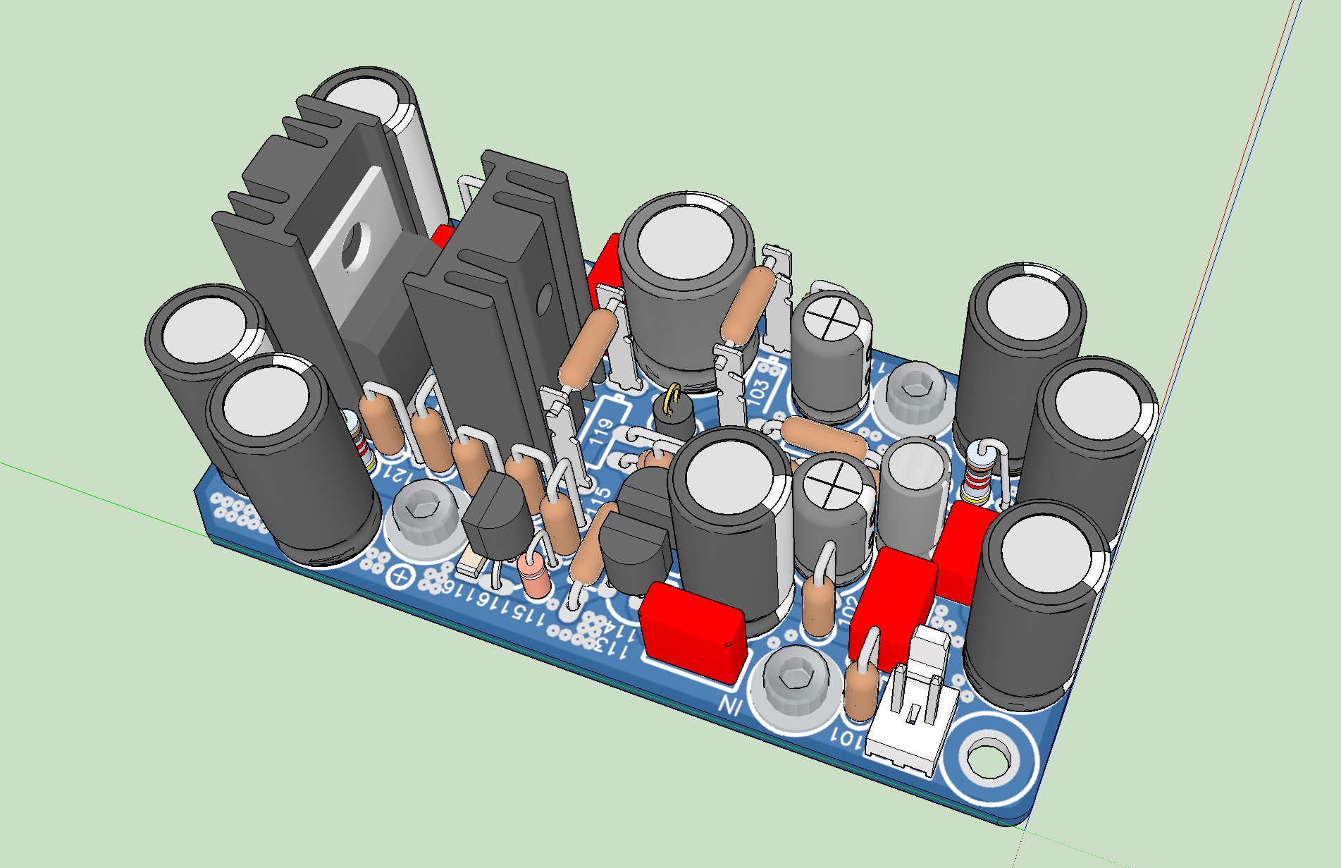
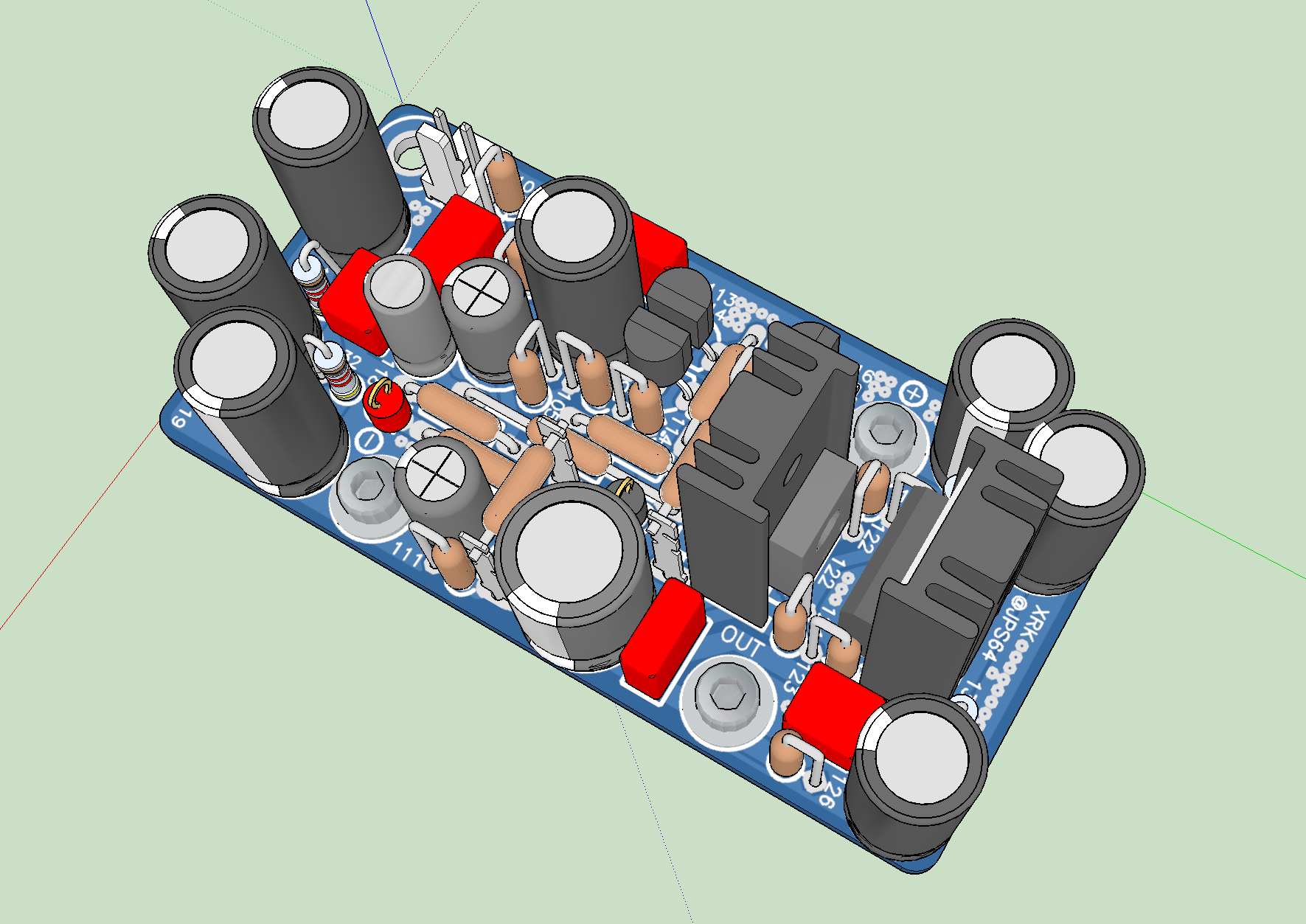
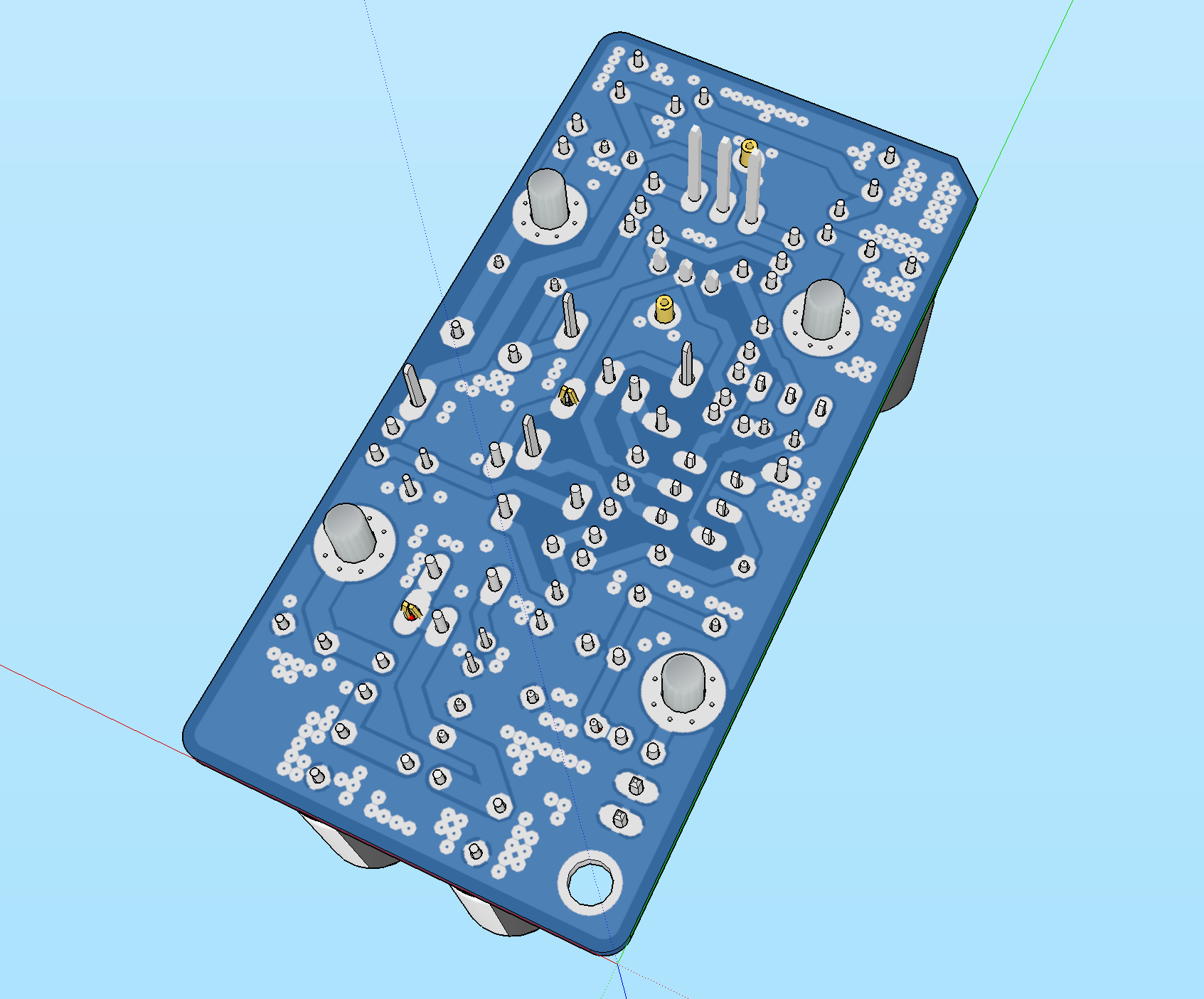
JPS64 is back and I should have new Gerbers tomorrow. Here are the new improved layouts for the TH board. With correct pin outs for M2X of course.

GB thread for the Melbourne is here:
https://www.diyaudio.com/forums/group-buys/333653-melbourne-daughterboard-m2x.html#post5690033
https://www.diyaudio.com/forums/group-buys/333653-melbourne-daughterboard-m2x.html#post5690033
JPS64 is working on an integrated motherboard that will hold the Melbourne daughterboards and provide 4 selectable inputs, volume pot, linear power supply with dual rail cap multiplier. It should be a pretty nice stand-alone preamp or
headphone amplifier. Will be offered as a GB later.
headphone amplifier. Will be offered as a GB later.
Hi X, I have 100s of KSA992, can I use it in place of BC557B? if so any changes to the circuit?
Regards
The other M2x daughter cards use a 220uF output coupling capacitor instead of C121=47uF here. The lower C will produce a measurable difference of a few degrees of phase shift at low bass frequencies. (Phase response at a roll off corner begins sooner, and slopes more gradually, than amplitude response; try it in a spreadsheet or a circuit simulator).
220uF x 600-800 ohm load, gives a longer timeconstant than 47uF, but it will have no effect upon M2 power-up "thumps". Why? Thanks to the even slower operation of M2's optical bias NFB loop. Connect a Kill-A-Watt (inexpensive mains wattmeter) between M2 and the mains, and take a video of its readings when you turn on the M2. Watts versus time. Surprise!
220uF x 600-800 ohm load, gives a longer timeconstant than 47uF, but it will have no effect upon M2 power-up "thumps". Why? Thanks to the even slower operation of M2's optical bias NFB loop. Connect a Kill-A-Watt (inexpensive mains wattmeter) between M2 and the mains, and take a video of its readings when you turn on the M2. Watts versus time. Surprise!
Thanks for reminding us that a 600ohm load needs a bigger coupling cap. I will make a note to update the BOM to 220uF although this Preamp can be optionally driven with DC coupling and cap would be bypassed.
I know that the M2 has a slow soft start ramp up - one of the best features. I have indeed measured the voltage as function of time and recall it takes about 45 seconds and if you play music it starts off at distorted Class B then slowly goes to Class A.
I know that the M2 has a slow soft start ramp up - one of the best features. I have indeed measured the voltage as function of time and recall it takes about 45 seconds and if you play music it starts off at distorted Class B then slowly goes to Class A.
We just checked and a 220uF/35V UFG, UKW, UFW cap fits the existing location (diameter 10.5 x 5mm pitch). This should cover it for those who decide not to go with DC coupled outputs.
Thanks for reminding us that a 600ohm load needs a bigger coupling cap.
It's a straightforward calculation which you and your engineering team could have performed back in November 2018 when this was written:
If you want to keep it as a Aksa Lender driving a 600ohm load, then use the M2X PCB and get the Melbourne daughterboard.
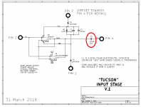
Or you could have simply copied that portion of the (well liked for good sonics) Tucson daughterboard, to name one example. The 220uF output coupling capacitor is plainly visible there on the schematic.
_
Attachments
- Home
- Amplifiers
- Headphone Systems
- The Melbourne Class A Headphone Amp and Pre-amp