mauropenasa said:Hi Graham, thanks for the interest.
....I creed that the "secret" is in the exact nature ( and composition ) of the back-EMF, given that the loudspeaker is not only a reactive element but overall a mechanical resonator ( and the Back_EMF come produced from this resonant dynamicses )....
....
True but to a degree.
It must be remembered - as was discussed in other threads before - that the back EMF is not an alien artifact, but the result of electrical to mechanical energy transduction.
Just as in an electrical motor there is a back EMF, it happens in a speaker. It is in fact the current injection *against* the back EMF what implies energy transfer (more precisely, the inner product of the current and voltage vectors).
Things depart from ideal due to a significant budget of converted electrical to mechanical energy diverted to non sound contributing sinks like suspension losses and the like.
To this must be added the unavoidable reactive components -both electrical and mechanical- like voice coil inductance, moving parts mass and elastic recovery (spider, cone surround) and the air itself which presents also a complex impedance. Reactive components are frequency dependent.
All the above efects are sumarized in the Thiele - Small speaker model.
In an ideal world, the only contribution to back EMF should be proportional to piston speed and thus air pressure, meaning the lowest practical amplifier output impedance should guarantee faithfull electrical signal to sound conversion.
Rodolfo
Hi Mauro,
More back-EMF musing.
Some high current (Mosfet) class-A designs present little natural damping; this means that there is much less likelyhood of interface distortion due to back-EMF impingement. Non-feedback and low damping amplifiers cannot react to loudspeaker back-EMF, and the crossover/loudspeaker cannot 'ring' against their output nodes.
They might not damp, but they don't interface distort.
The original JLH 10W tends to have about 30dB of damping, and this is not great for use with poorly damped loudspeaker systems, but it is an example of an amplifier that has the (common emitter) forward gain and band limiting of the first device outside of the series connected (common base sensed) global loop. Thus there may not be much damping, but with its wide open global bandwidth the reverse response of a JLH class-A is quite phase linear throughout the audio frequency range, and thus there is very little interface distortion. The induced output distortion is directly related to the (natural) back-EMF, as if the amplifier has a resistive output, and much less to any (un-natural) amplifier phase shift generated product.
These amplifier types can sound clean, but are less good for rock/pop because they lack dynamic loudspeaker control.
Cheers ......... Graham.
I share perfectly Your technical analysis and when I have different conclusions are only base on the results that get in my test.
By Ingrast: For me the problem is not much in the near analysis that you do of the loudspeakers, but as emulate their behaviour in static (and not impulsive) mode.
For All: While were " playing " with the measure setup of described in this thread, I have got an banal idea: Because doesn't try the effects of the back-EMF on a complex signal ? Have done any test that take root. In practice I have measured the amplitude of the odd harmonics first and after the back_EMF injection. The results are enough amazing: to the contrary thing of the 1KHz sine test, the amplifiers with output stage with tall Zout ( what to 1Khz it introduced a greater intermodulations ), have less modify the harmonic envelopment. The percentage of variation is potentially audible, do as the tendency to compress or extend the envelopment.
Notice as the "good old" JLH does part of improve in absolute, to the contrary thing of the classical topology. Naturally this is only an attempt of measure, but the first results give reason to the + "musical" topologies.
P.S. The better than this test is a TDA2030 shaped as variation of current dumping and piloted by a LM318...
Ciao
Mauro
Attachments
ingrast said:
Mauro:
I can understand you may feel disapointed for lack of feedback, may be even suspect unspoken interests are behind this. While some of the latter may be true to a measure, you should also be ready to notice a couple of points
1. You should be ready to acknowledge observations. I can remember a couple of posts from myself, and several others in the sense of noting your topology starts with a current mode output stage but ends in a voltage mode overall operation due to global voltage feedback.
While this configuration may be sonicaly good, it is not clear this is the result of a purpose or design. You failed to at least voice your oppinion with respect to this issue.
2. On the Hiraga test, basically what it does is exercise the amplifier under test output impedance. Here there are basically 2 possible extreme situations.
- A extremely low output impedance attained through large open loop gain and global feedback should provide good results. Note this implies the amplifier must be able to overcome a virtual short circuit at the back injected frequency, that is what low output impedance means in the end. If it is not capable of performing, then the whole chain gets disrupted.
- A no negative feedback design may perform equally well as long as the back injected signal does not intermodulate in the output stage. Again how much this is an issue depends on the output stage design and drive capability.
A final comment, I myself want to encourage your drive to experiment and share results. From this you benefit as much as all the rest of us. You may be certain to get feedback, questioning and encouragement as long as you are responsive.
Chau !!!
Rodolfo
Rodolfo,
Fully agree with your post. Mauro's research IS interesting, but it should also be realised that the audience for this type of work is probably not very large, so reactions my be few and long in between. keep up the good work Mauro!
I have received some info from Mr Hiraga about his test results, as we discussed before. They seem to match quite nicely with your observation that the good performers probably are either high feedback or very low feedback, but not the in-betweens. Interestingly, figure 3-2 in the article was produced by a rather traditional high-feedback design, the venerable Sony TA-N86 (of which I have two, hah!). What is also interesting in the Sony is that it has a switching power supply, so there would not be any 50/100 Hz interaction of the power supply with the impressed 50 Hz test signal. Thoughts?
Secondly, there is also a VERY good test curve, not published in the article, that basically is identical to the test signal, and is produced by one of Mr. Hiraga's personal MOS-FET designs with... low feedback!
The plot thickens!
Jan Didden
janneman said:I have received some info from Mr Hiraga about his test results, as we discussed before.
[...]
Interestingly, figure 3-2 in the article was produced by a rather traditional high-feedback design, the venerable Sony TA-N86 (of which I have two, hah!).
Thanks for finding out this info Jan.
janneman said:
...What is also interesting in the Sony is that it has a switching power supply, so there would not be any 50/100 Hz interaction of the power supply with the impressed 50 Hz test signal. Thoughts?
...
Jan Didden
Jan:
As long as the PSU rejection ratio is high this should not be an issue, but then again we are talking very low level phenomena (do we know? scale has not been settled as far as I know at least).
I should anyway place my bets on high feedback designs, taking into account that in the real world an audio amplifier has to drive reactive loads.
What this implies is the output stage driver must provide a signal that does not resemble (in extreme situations like transients) the actual desired signal, in order to get the desired output after factoring in load magnitude and phase angle.
This "precorrection" cannot be achieved without feedback, be it global or local to the output stage itself in an idealized emitter follower for example (implicit feedback).
The usual considerations in circuit design that lead to high performance Operational Amplifiers not necessarily translate to good performance audio (or power amplifiers with non resistive loads) because of this.
Rodolfo
For getting graph2, I think these 2 approach is right. But I think they won't sound the same. While the graph (with limited accuracy of the meter) looks the same, I suspect the high-feedback will contain more high order artifacts (which is not pleasant) than the low feedback approach.They seem to match quite nicely with your observation that the good performers probably are either high feedback or very low feedback, but not the in-betweens.
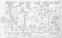
I don't know this amp. Anyone has schematic or topology that this Sony amp uses?the venerable Sony TA-N86
ingrast said:
Jan:
[snip]I should anyway place my bets on high feedback designs, taking into account that in the real world an audio amplifier has to drive reactive loads.
What this implies is the output stage driver must provide a signal that does not resemble (in extreme situations like transients) the actual desired signal, in order to get the desired output after factoring in load magnitude and phase angle.
This "precorrection" cannot be achieved without feedback, be it global or local to the output stage itself in an idealized emitter follower for example (implicit feedback).
The usual considerations in circuit design that lead to high performance Operational Amplifiers not necessarily translate to good performance audio (or power amplifiers with non resistive loads) because of this.
Rodolfo
Rodolfo,
Agree, but don't understand your last para. Hi-performance opamps are generally used with high feedback which would give the performance you mentioned above ('pre-distortion'). What do you mean?
Jan Didden
ingrast said:Jan:
[snip](do we know? scale has not been settled as far as I know at least).
[snip]Rodolfo
Scale on the fig 3 curves in the article is from +20 to -60dB.
Jan Didden
Jan, thanks for your precise statements ( that in departs confirm the theories of a lot of participants of the thread ) on the Hiraga test. Knows that my searches are of interest to some ( and that some reads my provocations ) me from the neccessary energy to find the time of behaviour my test.
Cash advance that the last test that I have proposeded is giving the better results that I never has seen in the tests of amplifiers. On account of the little data that I have furnished have the feeling that a few have understanded the course of this test. Per hour I am able only say that have found a relationship between the "real sound" and the measures simply amazing. to brief will look for to giving to all the data necessary to analysing my chart...
Ciao
Mauro
lumanauw said:[snip]I don't know this amp. Anyone has schematic or topology that this Sony amp uses?
Attachments
janneman said:
Rodolfo,
Agree, but don't understand your last para. Hi-performance opamps are generally used with high feedback which would give the performance you mentioned above ('pre-distortion'). What do you mean?
Jan Didden
The vast majority of OpAmp aplications feature resistive or just mildly reactive loads, meaning output voltage and current are mostly in phase and thus related by a constant scale factor.
This implies in turn the volage signal along the amplifying chain is a close copy of the desired signal except for scale (barring highly nonlinear amplifying stages not found in high performance well designed devices).
Rodolfo
This is not the case with the output stage drive signal and actual output stage voltage in the case of power amplifiers driving reactive loads, since the driver signal must be capable of elicit in the output devices, a current that does not resemble the signal voltage. This difference is what I was refering as "precorrection" and can only be achieved with feedback, which provides back information on the load's nature.
Note again that a simple emitter follower has implicit feedback in this sense.
janneman said:
Scale on the fig 3 curves in the article is from +20 to -60dB.
Jan Didden
I am afraid 80 dB of measurement range is not enough nowadays. Any amplifier featuring significant spurious output at and above a -80 dB relative to nominal signal is bound to show weaknesess in other tests.
Rodolfo
ingrast said:
I am afraid 80 dB of measurement range is not enough nowadays. Any amplifier featuring significant spurious output at and above a -80 dB relative to nominal signal is bound to show weaknesess in other tests.
Rodolfo
That may be true, but if you review the figures 3-3, 3-4 and 3-5 at the original article, you should be thankfull that the stuff below the lower limit is mercifully hidden!😉
Jan Didden
janneman said:
That may be true, but if you review the figures 3-3, 3-4 and 3-5 at the original article, you should be thankfull that the stuff below the lower limit is mercifully hidden!😉
Jan Didden
😀
This is because speaker's back EMF right? Opamp analysis and power amp analysis should be a bit different because of the load.The vast majority of OpAmp aplications feature resistive or just mildly reactive loads, meaning output voltage and current are mostly in phase and thus related by a constant scale factor.
But why this back EMF is not having more attention that it deserves? To me it is audibly very clear the difference when the speaker is taken to feedback system and when it is not.
My view is that back-EMF is a inimitably complex mix of both electrical and electromechanical energies.
The former being due to cable/crossover/driver circuit interactions, where electrical energy is stored and released with multiple time constants.
The latter is due to driver coil transduced/electromechanical cone/surround/air-spring/cabinet/room interactions.
Thus back-EMF is not purely driver related.
Hi Mauro, #82
You appear to be saying that the testing should relate to impulse testing, and not static.
I agree.
With steady sine-wave testing, all of the initial and complex multiple interactions are missed as they settle during the first cycle of reproduction.
Your test measurements are beginning to bear fruit. I wish I could be involved, but I must content myself with merely constructing what I believe will become my own 'medium feedback' 'music' amplifier that should be capable of better passing such tests; though of course no design can be perfect.
With reference to your 'back emf test.pdf'
I still believe that the amplifier load needs to be reactive (as per a crossover/dynamic loudspeaker equivalent) such that the amplifier is attempting to drive phase shifted load current related to input. It is the amplified 'input' that becomes distorted, and high NFB designs are less likely to show back-EMF induced weakness when the load remains predominantly resistive.
Of course I do realise that you are trying to establish a test, rather than mimic real life, but my concern is that the amplifier (signal) current remains relatively phase linear.
What is your slew rate limit ?
I should prefer to see something relating to a 40-50kHz bandwidth for future relevence, and not just 20kHz which could make poorer designs seem satisfactory.
Transients might be 20kHz filtered, but their momentary amplitude can still attempt to exceed rail levels such that the slew rate exceeds notional 20kHz filtered limits. This is where steady sinewave tested high feedback designs can generate 'phantom' errors when the global NFB becomes slew limited.
I also think it would be worthwhile noting the phase shift of each amplifier at say 20kHz, because some designers use internal pre-filtering to limit the effect of back-EMF induced NFB problems with their designs, and thus some that are 'musical' might have hf roll-off that actually reduces reproduction accuracy.
Cheers .......... Graham.
Graham, I foreseed your technical observations and share it.
Creditable to the JoseF_K help, to brief will publish my technical relationship and the detailed description of my test. Cash advance that my setup at the beginning is an attempt , and probably if had acted base on the "theorists" methods am not arrived to this results.
Of this will speak much. I believe that the " not-conventional "setup that am using even is able to underline the problem that you have punctually and perfectly place. Is an error produce this dynamicses? Perhaps. Of some the relationship between the measures and the results of listening confirms that this road is interesting.
The audio range( amplifier-speakers+EMF chain) ends to 20Khz? Perhaps. Even the TIM theories ( that use this waveform ) are able is questionable, given that impose to the amplifier a slewrate that theoretically ( 20-20Khz ) don't serve.
I have developed a setup that "isolate" a "global" behaviour of the "amplifier system" in presence of external perturbations. Because some amplifiers show traces of more of this problem? Slew limit? IMD? NFB?
In this forum there are persons with ability of analysis much better of the my ( as you ) that are able to give an answer.
Per hour, I have proposed a "primitive" setup ( perhaps is for this that works ) but in degree of makes oneself conspicuous some behaviours of an amplifier. The results are lifelike? All the better amplifiers by the "musical" point of view has an excellent behaviour to this test ( my reference to Mosfet doesn't foresee in the chart has variations of 0.05 % on all the harmonicas!). In my relationship that will publish will show as is is able improve " interface distortion " working on the "real dumping" and NFB...
Ciao
Mauro
Creditable to the JoseF_K help, to brief will publish my technical relationship and the detailed description of my test. Cash advance that my setup at the beginning is an attempt , and probably if had acted base on the "theorists" methods am not arrived to this results.
Transients might be 20kHz filtered, but their momentary amplitude can still attempt to exceed rail levels such that the slew rate exceeds notional 20kHz filtered limits. This is where steady sinewave tested high feedback designs can generate 'phantom' errors when the global NFB becomes slew limited.
Of this will speak much. I believe that the " not-conventional "setup that am using even is able to underline the problem that you have punctually and perfectly place. Is an error produce this dynamicses? Perhaps. Of some the relationship between the measures and the results of listening confirms that this road is interesting.
The audio range( amplifier-speakers+EMF chain) ends to 20Khz? Perhaps. Even the TIM theories ( that use this waveform ) are able is questionable, given that impose to the amplifier a slewrate that theoretically ( 20-20Khz ) don't serve.
I have developed a setup that "isolate" a "global" behaviour of the "amplifier system" in presence of external perturbations. Because some amplifiers show traces of more of this problem? Slew limit? IMD? NFB?
In this forum there are persons with ability of analysis much better of the my ( as you ) that are able to give an answer.
Per hour, I have proposed a "primitive" setup ( perhaps is for this that works ) but in degree of makes oneself conspicuous some behaviours of an amplifier. The results are lifelike? All the better amplifiers by the "musical" point of view has an excellent behaviour to this test ( my reference to Mosfet doesn't foresee in the chart has variations of 0.05 % on all the harmonicas!). In my relationship that will publish will show as is is able improve " interface distortion " working on the "real dumping" and NFB...
Ciao
Mauro
Graham Maynard said:My view is that back-EMF is a inimitably complex mix of both electrical and electromechanical energies.
The former being due to cable/crossover/driver circuit interactions, where electrical energy is stored and released with multiple time constants.
The latter is due to driver coil transduced/electromechanical cone/surround/air-spring/cabinet/room interactions.
Thus back-EMF is not purely driver related....
Yes Graham, that's what I pointed post #81. The correct analytical approach is by the way of the Thiele-Small model and extra elements like crossover network if present.
...I still believe that the amplifier load needs to be reactive (as per a crossover/dynamic loudspeaker equivalent) such that the amplifier is attempting to drive phase shifted load current related to input. It is the amplified 'input' that becomes distorted, and high NFB designs are less likely to show back-EMF induced weakness when the load remains predominantly resistive...
Cheers .......... Graham.
No, the resistive load for the test is OK. The idea is precisely to segregate under controled conditions what is nominal load and what is back EMF. With a resistive load and back injected external signal. you have precise control on what you are hammering back. If this back injection were contaminated with extra EMF sources (reactive, speaker), results should not be consistent or meaningful.
Rodolfo
- Status
- Not open for further replies.
- Home
- Amplifiers
- Solid State
- The many faces of distortion