Wesayo, I have been reading your thread for a while. I'm planning to go down a similar route. Vifa TC9, floor to ceiling line array, but it is going to be in a corner. Corner placement helps eliminate the front wall reflection and near side wall reflection. Of course, the most annoying ones are floor and ceiling, which is the whole point of the line array. So far, I've tried an expanding line array version with good success:
http://www.diyaudio.com/forums/multi-way/258246-corner-expanding-line-array-kef-q100.html
But that pesky ceiling reflection still persists. Anyway, to my question. What is the impact of rear mounting the drivers and then doing a roundover on the driver hole? Is there a reflection there? Would it be better to mount them flush? I'm curious if you did any studies when you designed the baffle. In the corner arrangement, I want the drivers as close to the side walls as possible and want to eliminate as many edges as possible.
Last edited:
I chose to do the back mount (very thin front baffle by the way, 6mm with a 8mm radius) after seeing the arrays from koldby on this forum.
I did not do my own research in the form of measurements but looked for results around the web. Sadly the pictures and measurements are gone now. It displayed a slight horn loading effect but the most striking thing was better off axis response and the peak on axis at 8 kHz was less prominent. Sadly I didn't save those measurements.
This was the thread I found: http://www.diy-hifi-forum.eu/forum/showthread.php?t=2157
I have found no detrimental effect though, I chose the thickness of the baffle and the radius by looking at the geometry in a cut trough in 3D:

It's almost a natural extension and doesn't stick out past the surround. Further on it flows into my enclosure shape.
I would not change anything regarding that choice if I had to do it again.
I did not do my own research in the form of measurements but looked for results around the web. Sadly the pictures and measurements are gone now. It displayed a slight horn loading effect but the most striking thing was better off axis response and the peak on axis at 8 kHz was less prominent. Sadly I didn't save those measurements.
This was the thread I found: http://www.diy-hifi-forum.eu/forum/showthread.php?t=2157
I have found no detrimental effect though, I chose the thickness of the baffle and the radius by looking at the geometry in a cut trough in 3D:
It's almost a natural extension and doesn't stick out past the surround. Further on it flows into my enclosure shape.
I would not change anything regarding that choice if I had to do it again.
Read this if you are interested in corner line arrays:Wesayo, I have been reading your thread for a while. I'm planning to go down a similar route. Vifa TC9, floor to ceiling line array, but it is going to be in a corner. Corner placement helps eliminate the front wall reflection and near side wall reflection. Of course, the most annoying ones are floor and ceiling, which is the whole point of the line array. So far, I've tried an expanding line array version with good success:
http://www.diyaudio.com/forums/multi-way/258246-corner-expanding-line-array-kef-q100.html
But that pesky ceiling reflection still persists. Anyway, to my question. What is the impact of rear mounting the drivers and then doing a roundover on the driver hole? Is there a reflection there? Would it be better to mount them flush? I'm curious if you did any studies when you designed the baffle. In the corner arrangement, I want the drivers as close to the side walls as possible and want to eliminate as many edges as possible.
The Murphy Corner-Line-Array Home Page
It is a very good idea if your rooms dimensions are suited for such a placement.
One of my felleow adiophile freinds has made such an array with Vifa TC9 in the corners and is very satisfied with it.
The low frequency boost you normally have to use is much less and the reflection problems are minimized.
Koldby
I have seen that one, Koldby. Though the driver choice is kind of disappointing, wouldn't you say?
Wesayo, the driver roundover flows nicely into the shape of the enclosure. Very nicely done. I may do some measurements of flush and rear mounting with roundover.
Wesayo, the driver roundover flows nicely into the shape of the enclosure. Very nicely done. I may do some measurements of flush and rear mounting with roundover.
I have seen that one, Koldby. Though the driver choice is kind of disappointing, wouldn't you say?
Certanly yes.
But the theory is valid and my freind has made it with the Vifa speakers..
Koldby
Some thought about the graph I posted earlier:

This was taken with a flat target and skipping the psychoacoustic steps in DRC.
I think what we see here is a Line array response to the flat target. The slight drop in high frequency might well be the non ideal line behaviour at higher frequencies.
Anyway, my target is slightly different from the above. I know I said I wouldn't comment to much on: how does it sound?
But I have to 😀. Just spend a while, eyes closed listening to a very broad collection of songs. Goosebumps all over. Very convincing imaging, real depth to the stage, but different in each recording. Like I hinted to before, this is more of a you are there than a they are here system. Boy am I glad I made these! The hobby might be over though (lol). What else is there to build after this?
The dynamics are unbelievable. At some parts they knock you off your seat. 😱
Okay, I'll try to contain myself again. But it's the best I've heard so far beside live music.
Cogratulations!Anyway, my target is slightly different from the above. I know I said I wouldn't comment to much on: how does it sound?
But I have to 😀. Just spend a while, eyes closed listening to a very broad collection of songs. Goosebumps all over. Very convincing imaging, real depth to the stage, but different in each recording. Like I hinted to before, this is more of a you are there than a they are here system. Boy am I glad I made these! The hobby might be over though (lol). What else is there to build after this?
The dynamics are unbelievable. At some parts they knock you off your seat. 😱
Okay, I'll try to contain myself again. But it's the best I've heard so far beside live music.
I am very tempted to say: I told you so😀😀😀😀😀😀

Koldby
Hi wesayso, I'm glad to hear you are enjoying the results of your efforts. The hobby of attending in-home concerts will never be over!
I'm puzzled by the tilted response. If the psychoacoustic target stage was bypassed and the postfiltering stage was set flat, then the response should look flat in REW. Would you mind posting the pre-DRC response? Also, I assume you are still using DRC Designer? Did you tweak any settings?
I'm puzzled by the tilted response. If the psychoacoustic target stage was bypassed and the postfiltering stage was set flat, then the response should look flat in REW. Would you mind posting the pre-DRC response? Also, I assume you are still using DRC Designer? Did you tweak any settings?
Here's the right response, no EQ:
I used a modified soft44100.drc template,
DLMinGain = 0.2
PTType = N (have to re-check this though, I re-opened the template today and it was on M, but I did do some processing for someone else after my session)
Settings in DRCDesigner, target flat and
LFCS=22% (min phase lower window: 35758)
MFCS= 22% (Min phase window exponent: 0.83)
HFCS= 14% (Min phase upper window: 36)
PLMaxGain=3.0 (though running it with lower setting had the same result)
Rest is set to default from DRCDesigner, LFP-EC=50%, MFP-EC=67%
wes...
i feel like a total amateur compared to you.....or to any of the guys here...so much research, so much data...all I did was stuff the driver in the shape...
I envy you sir 🙂 the knowledge...
Best of luck for the project mate....
Danny
i feel like a total amateur compared to you.....or to any of the guys here...so much research, so much data...all I did was stuff the driver in the shape...
I envy you sir 🙂 the knowledge...
Best of luck for the project mate....
Danny
Hey Danny, I was just wondering this week how your enclosures are doing?
On the knowledge part, I'm still learning, trying to absorb as much info as I can by reading a lot on this material. But it seems to work out, the more I learn, the better my speakers are sounding.
I feel confident enough to give some demo's now, I got a line of people waiting to hear them (lol).
I wanted to get some new measurements done today (because I switched from USB to Toslink on my DAC) but all I did was listen 🙂.
Thanks for the response. This is a new one for me 🙂. PLMaxGain of 2.0 or higher should be sufficient for flattening the frequency response shown in post 809. I think what you may need to do is use DRC exclusively rather than in conjunction with outside EQ. Try bypassing the ringing truncation stage first to see if this does the trick, (perhaps the initial eq used was not an ideal time-domain correction for a line array response) especially if you don't want to re-measure. Otherwise, a new non-eq'd measurement fed to DRC (with a PLMaxGain setting of 3.0 - 4.0) may be in order.
Once you have obtained a flat (smoothed) frequency response with the PT stage bypassed, simply engaging it should provide you with the elusive ideal "flat" response. At the very least, you'll be in a good position (with the PT stage bypassed) to experiment with the various target curves (using the PF stage) that the experts speak of.
Once you have obtained a flat (smoothed) frequency response with the PT stage bypassed, simply engaging it should provide you with the elusive ideal "flat" response. At the very least, you'll be in a good position (with the PT stage bypassed) to experiment with the various target curves (using the PF stage) that the experts speak of.
I'll first re-check what setting the PTType from M to N does in new measurements.
The pre-EQ I use does nothing detrimental to the response judging the group delay and phase graphs. In fact it helps to get it more right from what I can tell. That isn't the cause of a non flat response. It might be error on my part and I'll re-check. I wouldn't be surprised if I didn't end up with a totally flat response though, 50 drivers firing at once is kind of different from 2 to 6 drivers normally used 😀.
They will add up in response at frequencies below ~ 2000 Hz and above this the adding will be less than ideal due to comb filter effects. (center to center spacing of 85 mm)
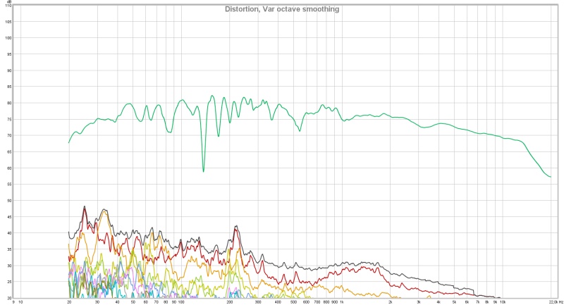
As you can see the initial un-EQ-ed response has a broad range going outside plus-minus 12 dB. That's the only reason for my pre-EQ.
There isn't a whole lot to fix for DRC on these arrays except for frequency response, I checked the graphs gating the measurement for both Phase and Group Delay of the EQ-ed lines and after DRC. The differences are very small.
Judging from the example graphs in the DRC docs the errors DRC needs to fix are usually way worse (for example a 3way with crossovers).
The pre-EQ I use does nothing detrimental to the response judging the group delay and phase graphs. In fact it helps to get it more right from what I can tell. That isn't the cause of a non flat response. It might be error on my part and I'll re-check. I wouldn't be surprised if I didn't end up with a totally flat response though, 50 drivers firing at once is kind of different from 2 to 6 drivers normally used 😀.
They will add up in response at frequencies below ~ 2000 Hz and above this the adding will be less than ideal due to comb filter effects. (center to center spacing of 85 mm)
As you can see the initial un-EQ-ed response has a broad range going outside plus-minus 12 dB. That's the only reason for my pre-EQ.
There isn't a whole lot to fix for DRC on these arrays except for frequency response, I checked the graphs gating the measurement for both Phase and Group Delay of the EQ-ed lines and after DRC. The differences are very small.
Judging from the example graphs in the DRC docs the errors DRC needs to fix are usually way worse (for example a 3way with crossovers).
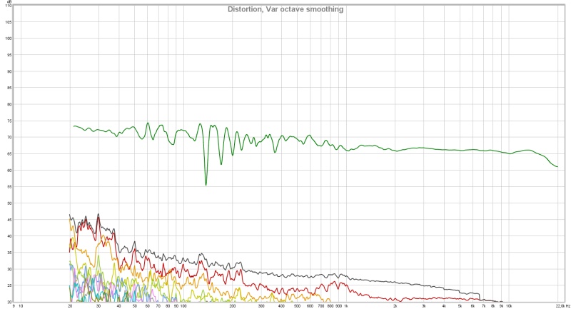
Looks good to me... 😉Here's the right response, no EQ:
I've seen worse to put it with some degree of understatement.
I like this better, Right side EQ-ed and Convolved:
Or a prettier smoothing and scale:

It's the least pretty side, no damping on side wall like the left side.
Or a prettier smoothing and scale:
It's the least pretty side, no damping on side wall like the left side.
Last edited:
Nothing changed yet, just showing the difference between right response without EQ and with EQ and convolver as a reply to esgigt...
By the way, how did you record those square waves? Would like to try that at some point...
By the way, how did you record those square waves? Would like to try that at some point...
Last edited:
I created the square waves in Audacity, then convolved them with a wav file of my corrected speaker response (nearfield).
Fun stuff this DRC, I'm getting closer and closer... now I just need to get the eyebrows right 😛

always wanted to use that picture
always wanted to use that picture
In search of the eyebrows I tried a few different curves:

Actually, the curve is the same, only the slope changes.
It's based on the Bob Katz curve with a corner at 1 KHz. In the lows I loosely follow JBL's recommendations. I've listened to it flat and various other ways.
A slight hump in the low end sounds most pleasing to me. Of the curves above the upper one, with the biggest drop on the high end is the most pleasing. I did expect the lower one to be the favourite but it is bright with most music.
The previous posted result with flat target was indeed with PTType set to "M".
But I did not get a flat response with it set to "N".
Didn't bother with more tests of that as my goal was to see the curves I made with listening tests in the past week. I wanted to see the curve I liked.
Distortion didn't change with the boosted low:
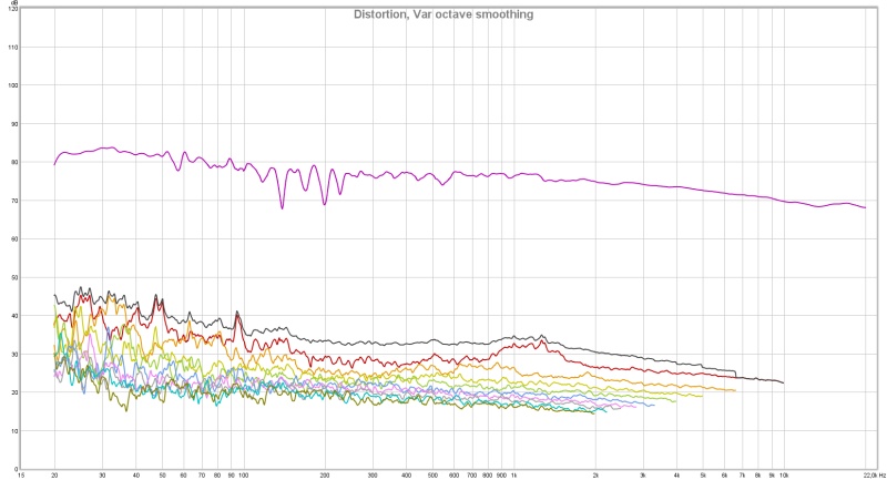
So far I'm impressed with the sound (understatement) and it looks like I get to keep the eyebrows in the music.
Actually, the curve is the same, only the slope changes.
It's based on the Bob Katz curve with a corner at 1 KHz. In the lows I loosely follow JBL's recommendations. I've listened to it flat and various other ways.
A slight hump in the low end sounds most pleasing to me. Of the curves above the upper one, with the biggest drop on the high end is the most pleasing. I did expect the lower one to be the favourite but it is bright with most music.
The previous posted result with flat target was indeed with PTType set to "M".
But I did not get a flat response with it set to "N".
Didn't bother with more tests of that as my goal was to see the curves I made with listening tests in the past week. I wanted to see the curve I liked.
Distortion didn't change with the boosted low:
So far I'm impressed with the sound (understatement) and it looks like I get to keep the eyebrows in the music.
- Home
- Loudspeakers
- Full Range
- The making of: The Two Towers (a 25 driver Full Range line array)