Your DSP is very impressive. Do you have a thread on it or more details on implementation? Like what DSP chip, what ADC/DAC chips etc? Very nice to design it for extra high headroom - as this allows +ve (boost) parametric EQ if needed (did I understand that correctly)? I tried building a custom 8 ch balanced output DSP and used the ADAU-1652 and AKM ADC’s and DACs (only to be burned by that choice when AKM’s facility’s burned down and there were no chips for 2 years).
You have a good point about using bandpass slot loading to reduce distortion and manipulate the acoustic response prior to electronics. Especially on the woofer array. One way that I reduced the frontal area is to turn the woofers 90deg in SLOB arrangement. It doesn’t need to be an open baffle (OB) and can be used in vented or sealed alignments as well. This allows the drivers to push the air out of a slot and opposed motion cancels inertial force and reverses suspension induced non linear distortion of one driver is flipped around. With 8x 6.5in woofers I was able to achieve equivalent cone area of dual 12in drivers in a moderately sized baffle at exactly 12in wide. The 178mm deep slot chamber formed a natural bandpass at 470Hz which I used with the electrical passive crossover to create a steep 4th order slope for the pride of a second order filter (components wise). For an active system it doesn’t matter as much.
Here is a front view of the speaker I have that uses opposed slot loading on 8x woofers turned 90deg to reduce the frontal area:

The opposed slot loading gives a low harmonic distortion in the woofer region as can be seen here about -55dB at 100Hz for 2Vrms:

You have a good point about using bandpass slot loading to reduce distortion and manipulate the acoustic response prior to electronics. Especially on the woofer array. One way that I reduced the frontal area is to turn the woofers 90deg in SLOB arrangement. It doesn’t need to be an open baffle (OB) and can be used in vented or sealed alignments as well. This allows the drivers to push the air out of a slot and opposed motion cancels inertial force and reverses suspension induced non linear distortion of one driver is flipped around. With 8x 6.5in woofers I was able to achieve equivalent cone area of dual 12in drivers in a moderately sized baffle at exactly 12in wide. The 178mm deep slot chamber formed a natural bandpass at 470Hz which I used with the electrical passive crossover to create a steep 4th order slope for the pride of a second order filter (components wise). For an active system it doesn’t matter as much.
Here is a front view of the speaker I have that uses opposed slot loading on 8x woofers turned 90deg to reduce the frontal area:
The opposed slot loading gives a low harmonic distortion in the woofer region as can be seen here about -55dB at 100Hz for 2Vrms:
Last edited:

Pardon my ignorance, but what is the advantage of a bandpass loaded 5" mid in the 500-2500 Hz range over a suitably filtered direct radiator?
The advantage and the beauty of the bandpass is an increased sensitivity which reduces necessary electric power, which reduces distortions. And the banpass as acoustic filter is filtering out nonlinear distortion (harmonics) as well. The result are improved acoustic properties of the loudspeaker as a transducer. The proper crossover filter for it does not changes anything in it`s properties.
Thanks! Unfortunately, there is no dedicated thread for the DSP. Two processor chips are being used - Xilinx FPGA for FIRs and ADAU1452 for the signal management and dynamics. Convertors are Cirrus Logic CS4272 codec and CS4385 dacYour DSP is very impressive. Do you have a thread on it or more details on implementation? Like what DSP chip, what ADC/DAC chips etc?
Some pictures about volumes, construction, et cetera ...


Is the rear chamber for the 8 inch driver an ~7 liter oblong box ? so absolutely cool and unique approach you took - did you have previous BP speaker construction experience ?
I want one BAD

I want one BAD
Last edited:
Thank you @grindstone
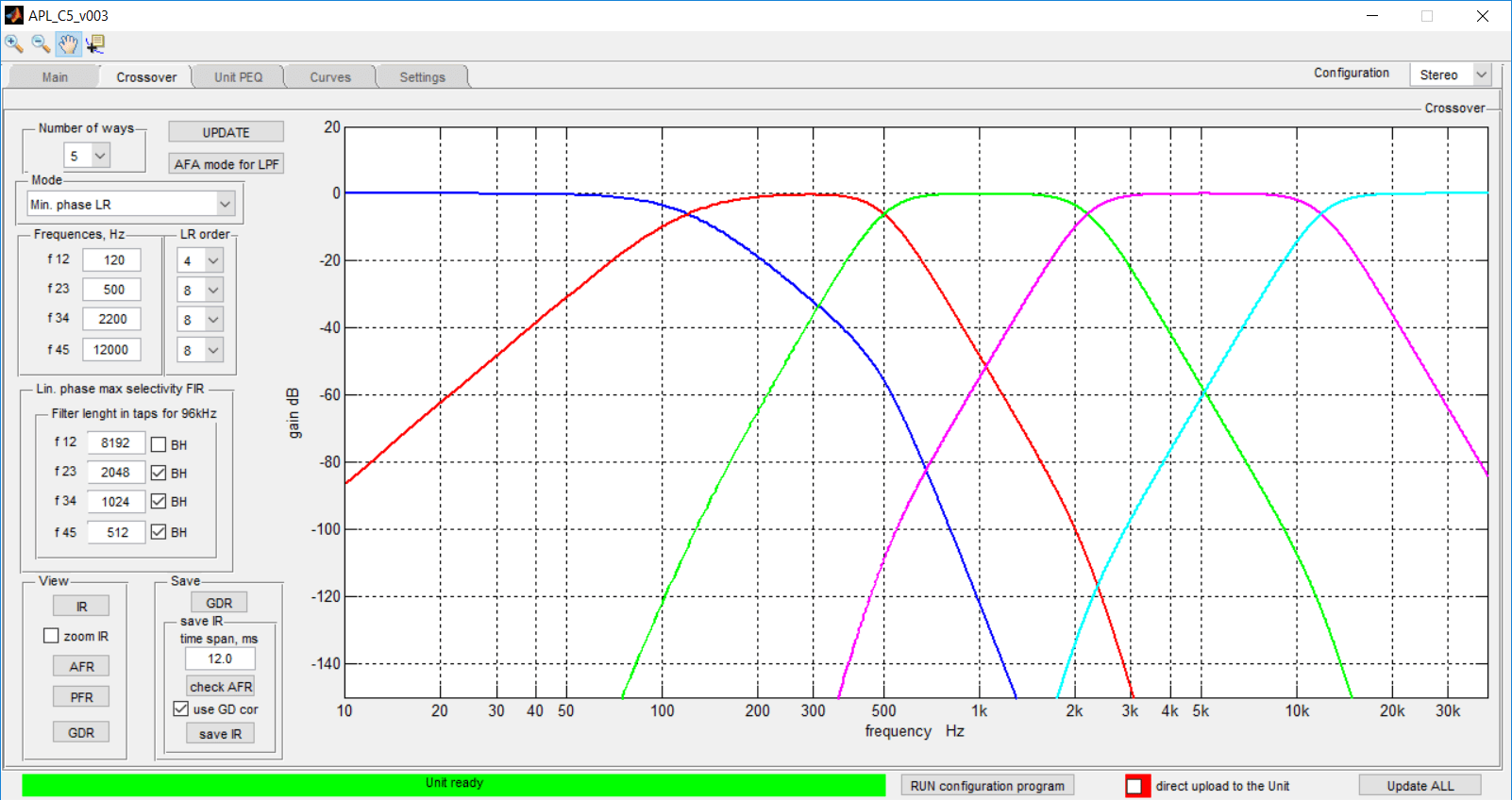
As we are in Multi-Way section such question may be actual.
Which is (or should be) the correct structure for the crossover? Here is 4 way example.

As we are in Multi-Way section such question may be actual.
Which is (or should be) the correct structure for the crossover? Here is 4 way example.
My guess would be 2, similar to this old Linkwitz inspired thread. Wouldn't 4 be quite close (or exactly the same) in comparison?
Option 2:

Option 4:

Exactly the same filter function as a result.
Option 2:
Option 4:
Exactly the same filter function as a result.
Looking at your filter schematic, I'd say you included a combination of 2 and 3 or 4 and 5. I can see the "bends" at each crossover, be it a lowpass or highpass. Just like they did in the thread I linked too 🙂.
So combine 4+5 and we're good to go.
(As long as our drivers are flat from zero to infinity 😀)
So combine 4+5 and we're good to go.
(As long as our drivers are flat from zero to infinity 😀)
Thank you @wesayso for joining this discussion and for pointing to the Linkwitz inspired thread.
Yes, the essence is in the sentence of @Robbintip : "ALL filters have to be applied in some way to ALL units."
The ideal crossover is being created such way with same phase responses in all ways and no need for any tweaking.
And the "ALL filters have to be applied in some way to ALL units" is hidden under "AFA mode for LPF" button on crossover`s control window above.
Which means 4 and 5 must be combined in the 6 : )
Why it is interesting? We have pretty much powerful FIR machines nowadays and it is easy to combine "All filters in all ways" and we can take into account a fact that particular driver is not flat but has its own characteristics / curve, Especially as in this bandpass project.
The Finite Impulse Response filter can contain Infinite number of curves combined in it.
A first order example with some level tweaks:

It can be seen in GD & Phase plot what this results in. 🙂
It can be seen in GD & Phase plot what this results in. 🙂
Interesting approach. What would be advantage over MEH which is using the same bandpass principle for all ways but tweeter?
Does bandpass mean that cabinet is made to function as low pass and high pass for a certain driver? -But in this case there is an extra cross-over to lower peaks outside the different passbands?
@Guerilla Yes, exactly as you mentioned. But we need to use an extra electrical crossover to reduce the out of band electrical power. And such two crossovers must be matched. We should chose an electrical crossover that is slightly steeper then acoustic one and set it as target. The electrical crossover should be found after that as a difference between acoustic crossover and the target.
@danibosn Thanks, good question. I had experience with nice MEH example from Danley.
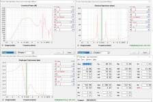
Here are measured curves of the 3d way of they system (two speakers, L R, hope you are finding them beautiful and too much similar for ordinary world : ) ):

Then 8th order crossover`s target was chosen:

And such filters were necessary to meet the targets:

@wesayso Thank you for your 1st order example. I did not think it will have such nice sum curve. But the 1st order should be too much insufficient as the displacement of the speaker`s membrane is increasing by 12 dB/oct when frequency is going down, it means, the crossover should be 12 dB/oct at least, 2nd order : )
@danibosn Thanks, good question. I had experience with nice MEH example from Danley.
Here are measured curves of the 3d way of they system (two speakers, L R, hope you are finding them beautiful and too much similar for ordinary world : ) ):
Then 8th order crossover`s target was chosen:
And such filters were necessary to meet the targets:
@wesayso Thank you for your 1st order example. I did not think it will have such nice sum curve. But the 1st order should be too much insufficient as the displacement of the speaker`s membrane is increasing by 12 dB/oct when frequency is going down, it means, the crossover should be 12 dB/oct at least, 2nd order : )
- Home
- Loudspeakers
- Multi-Way
- The making of the singing loudspeakers