i try to compare the pcb pics by Harry (post 411) with the Lt spice file.
so maybe it is not a new information 😉
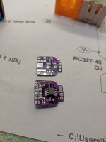
GND and out at the bootstrap adapter pcb is at the Resistor R3, R4 on the end of the LT1010 - so your M2OPS.
pic 1

Diodes D1, D2 are not existing BZX84C15L -15v Zener diodes. Rfb1 (1k) and Rfb(19k) must be on your Whammy pcb.
pic 2

chris
so maybe it is not a new information 😉
GND and out at the bootstrap adapter pcb is at the Resistor R3, R4 on the end of the LT1010 - so your M2OPS.
pic 1
Diodes D1, D2 are not existing BZX84C15L -15v Zener diodes. Rfb1 (1k) and Rfb(19k) must be on your Whammy pcb.
pic 2
chris

Was the LTSpice bootstrap circuit originally for the Whammy?
Assume for the M2OPS a 3K3 to earth on the -ve input would be used and 47K global feedback with 470K local on the OpAmp.
I'd model/ validate this myself with an 828, but I don't have a laptop that will run LTSpice or a Spectrum Analyser to test the complete amp
Assume for the M2OPS a 3K3 to earth on the -ve input would be used and 47K global feedback with 470K local on the OpAmp.
I'd model/ validate this myself with an 828, but I don't have a laptop that will run LTSpice or a Spectrum Analyser to test the complete amp
oh yes ....i see...was too late yesterday...Look carefully. 🤓
Patrick
it is written on the bootstrap pcb ---> D1, D2 with the diodes printed 15 - Harry soldered the zeners in..
sorry
Attachments
im still not woken up.......still have my "schematic" of my RC car in the head(Awesomatix A800R)
😉
....check this this week
😉
....check this this week
Hi DanWas the LTSpice bootstrap circuit originally for the Whammy?
Assume for the M2OPS a 3K3 to earth on the -ve input would be used and 47K global feedback with 470K local on the OpAmp.
I'd model/ validate this myself with an 828, but I don't have a laptop that will run LTSpice or a Spectrum Analyser to test the complete amp
sorry, but what are you talking about?
do you have a M2OPS?
have done the complete amp?
AFAIK the bootstrap adapter pcb should help to use a higher rail for an existing op amp - without damage the opamp - to us a bigger output swing and get a better output power over the output MOSFETs.
I'm getting read to start building my M2OPS using mixed feedback with Toshiba 2SK3497/2SJ618 FETs. Should I use the values list in values listed on the diagram in the mixed feedback instructions?
To avoid confusion, post the schematics and BoM you are using.
For example, I have no idea what opamp you intend to use.
We'll take it from there.
But it is 2 years already.
My memories don't go back so long these days.
Patrick
For example, I have no idea what opamp you intend to use.
We'll take it from there.
But it is 2 years already.
My memories don't go back so long these days.
Patrick
Dan,
Thank you for the information. I see that a few people have used the OPA604 opamp. Is there an advantage to using that opam over the 551?
Thank you for the information. I see that a few people have used the OPA604 opamp. Is there an advantage to using that opam over the 551?
Matter of taste.
There are fans for the 551/552.
www.diyaudio.com/community/threads/the-m2-output-stage-in-class-a-b-and-maybe-a-power-whammy.390636/post-7166204
And it has more voltage headroom.
Patrick
There are fans for the 551/552.
www.diyaudio.com/community/threads/the-m2-output-stage-in-class-a-b-and-maybe-a-power-whammy.390636/post-7166204
And it has more voltage headroom.
Patrick
Does anyone know why it's necessary to change the feedback layout with a bootstrapped front end? (Removal of local/ mixed feedback)
I'm also in the dark as to why there's no series or shunt (input loading R) at the input pin. I'm guessing that a 1K series and a 47K shunt would be appropriate for an OPA828, maybe a 100K shunt?
I did find an older version of LTSpice that I could run. Both the mixed feedback and the new proposed layouts appear to work, the mixed feedback layout gives less gain and does require the 3k3 input series resistor. If I reduced to below 2k then I got clipping.
551 can take a constant ±30V, 604 is rated at ±24V. To these ears 604 is miles better, YMMV, etc.
828 was released in 2017 (I think). It is the absolute SOTA but will only tolerate up to ±18V, hence the desire for that little Bootstrap daughter board.
First Datahseet entry of AD828 is 1993 -Analog device
operation voltage +/-15V
OPA828 is from TI --> first entry December 2022
oparation Voltage +/- 18V
- Home
- Amplifiers
- Pass Labs
- The M2 Output Stage in Class A/B, and maybe a Power WHAMMY?