these days I only have time for brain-dead/plug and play kits requiring no research or brain power other than building it.
Then this is not for you, I am afraid.
You are much better served by other LU1014 circuits published here.
Patrick
Last edited:

Clever and crystal-clear as always Patrick👍
Incidentally, Patrick just gave you suitable component values for the amp circuit. Just copy those from the test-rig presented here to the amp circuit shown in the first article and you are good to go😉
Incidentally, Patrick just gave you suitable component values for the amp circuit. Just copy those from the test-rig presented here to the amp circuit shown in the first article and you are good to go😉
At last, someone is interested in Spice and not just build blindly.
This is the starting point that allows you to adapt to your needs.
For example you can lower voltage and increase current for 4R loads.
You can also choose a more powerful cascode device, such as IRFP150, and run more voltage/current/ dissipation.
You can check power dissipation in the LU1014 as well as the cascode device, etc.
But in the end, your LU1014 and cascode device will be different from the model (different Vgs, Yfs, etc.).
So to obtain the absolute optimum, you will have to measure in circuit, and be prepared to change values, as Nic did.
The reward is of course very low distortion without using any negative feedback.
If you have listened to one, you will know why.
So, have fun with Spice. Cost you nothing. 🤓
Patrick
Attachments
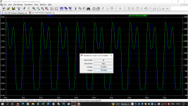
Working on limiting this a bit
Why ? It is perfect.
Unless you see ringing with reactive load.
Patrick
Is it necessary to have a distortion analyser before you can build this circlotron ?
The triode cell in this circuit is only a variation of that used by Nelson in Zen Variation 9.
So I can only quote from him:
https://www.passdiy.com/gallery/amplifiers/zen-variations-9
"I made reference to choosing the value of R3 to get the lowest distortion.
The best way to do this is to use a 5 ohm power potentiometer and measure the distortion for lowest possible value
This requires a distortion analyzer......
Since most of you don’t have a distortion analyzer, I have an alternate method of determining the value of R3.
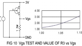
This is based on the Vgs value of the Lovoltech LU1014 JFET in the test setup of figure 10.
Using a 3 volt supply capable of greater than an amp, measure the Vgs of the device while the transistor case is still near room temperature.
Most of them will sit between 1.0 and 1.1 volts, and you can use the graph to estimate the best value of R3 usually between 1 and 3 ohms."
R3, in parallel with R1,2 (each 2ohm) in ZV9, is equivalent to the drain resistor (Rd1,2) in our circuit.
So you can use the same test setup in Fig.10 of the ZV9 article, to determine the optimum value of R3, and hence Rd.
Note that the bias used by Nelson is between 1.6~2A. So the dissipation of the Cascode device is ~40W.
Different from the ZV9, you can easily adjust the bias independently in the circlotron via the Vbias.
The best approach is to use a battery and a potentiometer first to set Vbias at room temperature.
Note down this Vbias value and use this to calculate the components in the bias compensation circuit as posted above.
Patrick
.
The triode cell in this circuit is only a variation of that used by Nelson in Zen Variation 9.
So I can only quote from him:
https://www.passdiy.com/gallery/amplifiers/zen-variations-9
"I made reference to choosing the value of R3 to get the lowest distortion.
The best way to do this is to use a 5 ohm power potentiometer and measure the distortion for lowest possible value
This requires a distortion analyzer......
Since most of you don’t have a distortion analyzer, I have an alternate method of determining the value of R3.
This is based on the Vgs value of the Lovoltech LU1014 JFET in the test setup of figure 10.
Using a 3 volt supply capable of greater than an amp, measure the Vgs of the device while the transistor case is still near room temperature.
Most of them will sit between 1.0 and 1.1 volts, and you can use the graph to estimate the best value of R3 usually between 1 and 3 ohms."
R3, in parallel with R1,2 (each 2ohm) in ZV9, is equivalent to the drain resistor (Rd1,2) in our circuit.
So you can use the same test setup in Fig.10 of the ZV9 article, to determine the optimum value of R3, and hence Rd.
Note that the bias used by Nelson is between 1.6~2A. So the dissipation of the Cascode device is ~40W.
Different from the ZV9, you can easily adjust the bias independently in the circlotron via the Vbias.
The best approach is to use a battery and a potentiometer first to set Vbias at room temperature.
Note down this Vbias value and use this to calculate the components in the bias compensation circuit as posted above.
Patrick
.
Attachments
- Home
- Amplifiers
- Pass Labs
- The LU1014 Circlotron Power Buffer