I've been wanting to make another Circlotron for a while; I built my first one in the early 80's.
I have 60 unmatched LU1014, rather than going through the tedious process of matching up a quad set, I might give this a go as I have an untouched matched quad set of THF51S from Watanabe sitting in a draw.
OK, the H3 probably won't be as low, but it can have plenty of grunt to drive my inefficient speakers - 86dB 3R.
Apologies for the off topic.
 Schematic removed by moderation at poster's request.
I have 60 unmatched LU1014, rather than going through the tedious process of matching up a quad set, I might give this a go as I have an untouched matched quad set of THF51S from Watanabe sitting in a draw.
OK, the H3 probably won't be as low, but it can have plenty of grunt to drive my inefficient speakers - 86dB 3R.
Apologies for the off topic.
Schematic removed by moderation at poster's request.
Last edited by a moderator:
Just for clarification, the above schematic has nothing to do with XEN.
Please remove the XEN logo before you change anything from the original
Or draw you own with LTSpice , etc.
Patrick
Please remove the XEN logo before you change anything from the original
Or draw you own with LTSpice , etc.
Patrick
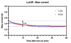
Thanks to the temperature-compensated LU1014 Vgs, the bias of the amplifier remains constant even with the increase in temperature of the heatsinks.
There is no need to wait for sonic bliss after turn-on, and there is no danger of thermal runaway.
There is no need to wait for sonic bliss after turn-on, and there is no danger of thermal runaway.
Attachments
Maybe you can also show us what the bias drift looks like without the compensation circuit ?
🤓
Patrick
🤓
Patrick
^ +1 - Yes, please. That would definitely help me understand a bit better how you're correcting / adjusting for the temco. (I think).
I don't believe I conducted this specific experiment, at least not with the optimized final circuit mounted on the larger heatsinks. Most of the measurements I performed were on a test rig with an undersized heatsink, but they were primarily done with the compensation circuit in place.
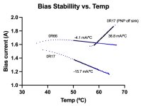
However, I did carry out an experiment that effectively demonstrates why it is important to use temperature compensation in this amplifier circuit and adjust it based on the specific circuit details/implementation. In these measurements, I monitored the bias current and heatsink temperature for amplifier circuits initially biased at around 1.6A at ambient temperature. I suspected that the required compensation depended on the value of the LU1014 drain resistor (Rd), so I recorded measurements for two different Rd values (0R17 and 0R66).
As an afterthought during the second measurement (0R17), I removed the temperature sensing transistor from the heatsink and allowed it to cool down to ambient temperature. By doing this, I effectively restored the initial bias and eliminated temperature compensation. Subsequently, I turned the circuit back on and continued recording the bias current and temperature. Without compensation bias current rises rapidly (approximately 40 mA/ºC).
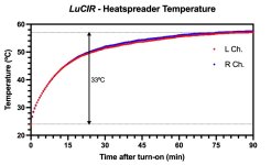
Assuming that the coefficient of 40 mA/ºC does not vary significantly with Rd (although this may not be a safe assumption), the bias current of the constructed amplifier would increase by approximately 1.3A due to the 33 ºC temperature rise.
The exact duration of this increase and where it would stabilize would need to be determined through further experimental investigation on the actual amp. Maybe I can find the time to do the test one of these days.
However, I did carry out an experiment that effectively demonstrates why it is important to use temperature compensation in this amplifier circuit and adjust it based on the specific circuit details/implementation. In these measurements, I monitored the bias current and heatsink temperature for amplifier circuits initially biased at around 1.6A at ambient temperature. I suspected that the required compensation depended on the value of the LU1014 drain resistor (Rd), so I recorded measurements for two different Rd values (0R17 and 0R66).
As an afterthought during the second measurement (0R17), I removed the temperature sensing transistor from the heatsink and allowed it to cool down to ambient temperature. By doing this, I effectively restored the initial bias and eliminated temperature compensation. Subsequently, I turned the circuit back on and continued recording the bias current and temperature. Without compensation bias current rises rapidly (approximately 40 mA/ºC).
Assuming that the coefficient of 40 mA/ºC does not vary significantly with Rd (although this may not be a safe assumption), the bias current of the constructed amplifier would increase by approximately 1.3A due to the 33 ºC temperature rise.
The exact duration of this increase and where it would stabilize would need to be determined through further experimental investigation on the actual amp. Maybe I can find the time to do the test one of these days.
Attachments

The temperature rising rate is depending on the total heat dissipation, heatsink Rtha, and heat capacity of the heatsink.
It should not be circuit details dependent.
But of course the dT between sink and LU1014 junction is depending on dissipation of the LU1014 itself.
Patrick
It should not be circuit details dependent.
But of course the dT between sink and LU1014 junction is depending on dissipation of the LU1014 itself.
Patrick
What I say is that the apparent dI/dT rate (change in bias current per unit temperature) is circuit dependent as documented specifically for Rd in the figure.
Fortunately, it appears to vary very little between different (matched) LU1014Ds🙂
Fortunately, it appears to vary very little between different (matched) LU1014Ds🙂
@NicMac - Thank you for posting your results! 🙂
I don't want to take the discussion too far off track. As is clear, I am a total novice.
Do you have any insight as to why at the same starting bias current of 1A6 the heatsink temps began at ~57C (for the experiment w/o the PNP on the heatsink)? I read that you allowed the heatsinks to cool to ambient between experiments, correct? Am I misinterpreting?
Edited for clarity.
great idea!Tired of repeatedly soldering and desoldering various combinations of low-value power resistors, I opted to create a straightforward, adjustable precision power resistor. This resistor consists of a series of 20 pieces of 0.05R resistors (0612, 1W, 1% tolerance). The resistance is adjusted using jumpers, employing two to reduce contact resistance. Consequently, the resistance can be set anywhere from 0 to 1R in 0.05R increments, with a nominally rated power of 1-20W depending on the chosen resistance.
I constructed two of these resistors and verified their functionality by measuring the voltage drop across the resistor while maintaining a constant current of 0.5A. The measured resistance was consistently approximately 15mR higher than the nominal value, likely due to the resistance introduced by the jumpers. This additional resistance was found to remain relatively constant and unaffected by the set resistance value.
The variation in resistance between the two resistors across different settings was determined to be 0.12% with a tolerance of +/-0.21%.
Is this amp a concept or something that will have some PCBs available?
What matching values are you looking for for best performance?
Did you evaluate the amp at lower rails lower/lower power (say ~+/-20 or 25VDC)?
thanks
I allowed the temperature sensing transistor to cool down. Not the heatsink - to lazy to wait for that to cool down properly.Do you have any insight as to why at the same starting bias current of 1A6 the heatsink temps began at ~57C (for the experiment w/o the PNP on the heatsink)? I read that you allowed the heatsinks to cool to ambient between experiments, correct? Am I misinterpreting?
I/we will likely make PCBs and properly matched actives available at some point, but not anytime soon. The basic circuit is shown in Patrick's paper and I hope impatient builders will try to make their own implementation - possibly better than mine 😉Is this amp a concept or something that will have some PCBs available?
Mine are possibly matched for both Vgs and Yfs to 0.1%, at temperature and across the whole current range. If you don't care for best H2 cancellation you can properly get away with less well matched devices.What matching values are you looking for for best performance?
The amp sounds and measures just fine with lower rail voltages, but remember that the cascoded triode cell eat up a fair share.Did you evaluate the amp at lower rails lower/lower power (say ~+/-20 or 25VDC)?
The amp sounds and measures better at higher currents, but look out for the heat dissipation limits of the LU1014
Nic,
I didn't see any component values in the euvl writeup, maybe I missed something, otherwise it's going to be hard to create a working amp.
thanks
I didn't see any component values in the euvl writeup, maybe I missed something, otherwise it's going to be hard to create a working amp.
thanks
I had good results in creating a low value variable resistance using a nichrome wire adjusted using a modified connector block as a wiper.Tired of repeatedly soldering and desoldering various combinations of low-value power resistors, I opted to create a straightforward, adjustable precision power resistor. This resistor consists of a series of 20 pieces of 0.05R resistors (0612, 1W, 1% tolerance). The resistance is adjusted using jumpers, employing two to reduce contact resistance. Consequently, the resistance can be set anywhere from 0 to 1R in 0.05R increments, with a nominally rated power of 1-20W depending on the chosen resistance.
I constructed two of these resistors and verified their functionality by measuring the voltage drop across the resistor while maintaining a constant current of 0.5A. The measured resistance was consistently approximately 15mR higher than the nominal value, likely due to the resistance introduced by the jumpers. This additional resistance was found to remain relatively constant and unaffected by the set resistance value.
The variation in resistance between the two resistors across different settings was determined to be 0.12% with a tolerance of +/-0.21%.
https://www.diyaudio.com/community/...lower-and-amplifier-build.349081/post-6078261
Because those values were the subject of all the experiments that Nic went through.I didn't see any component values in the euvl writeup .....
So you'll have to wait for the whole story.
As a starter, you can also take Nelson's triode cell in Zen V9.
Which was also our starting point.
Vbias will vary anyway with the JFETs you use and the bias you choose.
Patrick
Incidentally, as in any circlotron, you will need 2x floating power supplies.
The voltage will be limited by the dissipation of the cascade NMOS.
Dissipation in the LU1014 will limit the maximum bias.
Patrick
The voltage will be limited by the dissipation of the cascade NMOS.
Dissipation in the LU1014 will limit the maximum bias.
Patrick
- Home
- Amplifiers
- Pass Labs
- The LU1014 Circlotron Power Buffer