alexmoose said:Please tell me where I am wrong and why
Plate dissipation for EL34 types is 25W not 30W.
tubelab.com said:
Possibly! I have had two voltage related failures. Both were 6L6's and both were AC voltage related (not DC). The first was a guitar amp that had a miswired load. The two 8 ohm speakers were in series, but connected to the 4 ohm tap. It was a P-P amp that I had built earlier. The owner had put in new speakers, and wired them in series because he said it sounded better. He brought the amp to me because "it screamed at him" sometimes when he played it loud. The screaming sound turned out to be an arc from pin 3 (plate) to pin 2 (grounded filament) INSIDE the base of the "Audio Glassic" blue glass 6L6. I replaced the tube, and after discussing with the owner, decided to run the 16 ohm speakers on the 8 ohm tap. No further issues were seen. That amp runs 430 volts of B+ and about 400 volts on the screen.
I saw another 6L6 arc over between the pins on the outside of the base, eventually carbonizing the tube base and the socket. This was a stereo amplifier that was playing at high volume when the load was accidentally disconnected. Replcaing the output tubes and socket fixed the amp.
I have not experienced and DC voltage related issues with pentodes, or triode wired pentodes. Despite my reputation for extreme testing, I don't really hammer tubes too hard in normal operation.
It is interesting to note that the 807 and the 6BG6 are closely related to the 6L6GB. They have the plate brought out to the top cap. The plate voltage spec for these tubes is considerably higher, indicating that the internal structure is capable of a higher voltage.
I have seen a voltage related runaway condition occur in Sovtek 300B tubes. The specs printed right on the box claim that the tube can handle 450 volts. Some can, some can't. The ones that can't will go into a runaway condition where you can't shut the tube off even with -150 volts on the grid. Upon investigation it seems that these tubes have some filament wires exposed above the end of the control grid winding. This allows a path from the filament to the plate that does not pass through the grid.
I've seen carbon arcing on large tonage chillers that I work on. Had an old Westinghouse make a hell of a bang once (scared the heck out of me). Usually on 1000H.P. plus machines running on 4160v 3 phase with accross the line starting. I shipped some ST shaped 6BG6G's to a guy in MI. He won't tell me what his plans are yet. I have been thinking about a 807 project. I have collected some NOS Jan 1625"s which I understand to be the same tube only with a 12v heater which can be used on 6v much like a 12A**. I've got a book full of (off the beaten path designs) that has an interesting PP with a 6SL7 in the front end. Have you ever tortured any 807's or 1625's? If you want to and have the time, let me know and I'll send you some. From what I've heard there bullet proof. Jay
I have collected some NOS Jan 1625"s which I understand to be the same tube only with a 12v heater which can be used on 6v much like a 12A**.
This is only part true. The 1625 is a 12 volt 807 with a different base, however it does not have a tapped heater like a 12AX7. You will need a 12 volt transformer to use this tube.
Have you ever tortured any 807's or 1625's?
I have boxes full of 1625's still in the US ARMY boxes. I also have a large box full of 807's. I had a pair of NOS GE 807's all set up for experimentation when hurricane Wilma came along and spoiled the party. We had no electricity for almost 3 weeks, and all sorts of junk got piled in my lab. I never got back to the 807's. They are still on the corner of my bench.
So then if I send 410v to both the plate and the grid, the grid will be drawing (8w/410v) ~19ma and then each plate will be drawing around (30w/410v) ~73ma. is this the correct thinking?
Pentode mode is usually done like you say, with a few additions. If you apply 410 volts to the plate you should adjust the bias such that the plate current is about 60 mA (25 watts as mentioned), then with 410 on the screen grid (usually through a small resistor) measure the screen current (by checking the voltage across the resistor) and compute the screen dissipation. If it is less than 8 watts you are OK. If it is too high you need to lower the screen voltage. Most pentode fans claim that you will get better sound if the screen voltage is regulated. This appears to be true with some tubes and the EL-34 is one of them.
That's enough of the theory stuff. I have the new amp all set up on the bench. It still has the JJ EL-34's in it. It took me 5 minutes to wire in a switch that lets me flip from triode to UL to pentode. Yes I tell everybody NOT to flip the switch with the power on. (I have been puting these switches in my guitar amps for years) Well I am sitting here flipping the switch at full volume to compare the sound (nothing bad has happened, but you are warned). I have decided that I prefer the UL sound for loud music, and triode mode for simple vocals. I can play it louder in UL than I can in pentode mode. Pentode mode has audible bass distortion, possbly caused by my speakers. Cathode feedback is ON for all tests (I put a switch on that too).
The screen grid dissipation? With my normal B+ of 430 volts (about 390 across the tube) the screen grid draws 6.5 mA for about 2.5 watts on the screen, not melting anything here.
I installed the jumpers in the power supply to pump the B+ up to 475. Now the screen is getting 440 volts (35 volts across the cathode resistor) and the plate is getting 430 volts (35 lost in cathode resistor and 10 in opt) my screen current is now 7.5 mA for a screen dissipation of 3.3 watts. These tubes are drawing 55 mA for a plate dissipation of 24 watts. Everything is operating within the published ratings. For reference the cathode resistor is 560 ohms. If you run similar voltages you can use the same value.
The Svetlanas drew more current in the previous testing.
Next I popped in 6L6's and repeated the test. I went straight for the 475 volt test. Screen current is a wimpy 2.5 mA for a dissipation of 1.1 watts. Plate current is 65 mA for a plate dissipation of 28 watts. Close to the edge, but these tubes are the same ones that I had glowing with 45 watts previously. I intend to abuse this pair to see how they hold up. They have already been in a Fender Bandmaster for over a year and survived! These were Ruby tubes brand sold in a music store for guitar amp use. They are Chinese made by Shuguang, I have more on order.
Based on these tests, I say hook your power supply to the screen through a 100 ohm resistor and check the current, you will probably be OK.
Most interesting, Tubelab. As I said elsewhere, other folks' experience is cheaper!
Just to add another bit: Through the years I have often frowned at the sloppy finish between the bottom wafer and the pins. There sometimes does not appear to be real care to keep things consistent. In some cases I found the ends of un-cut-off connecting strips so close to other conductors that I feared the worst. Ratings for maximum voltages based on the tube proper construction itself become meaningless if a much smaller space between conductors occur at the bottom than "inside", sometimes with pointed ends glaring at each other "nose-to-nose"! The same went for the wires running between glass to pins in appropriate tubes, as you found. I am sure you must also have experienced this.
Regards.
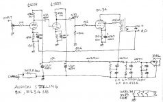
Tubelab Sir, attached is a schematic of Audion Sterling EL34. How often I wondered why on earth does it use the additional gain stage that your design does not have. And those 2 gain stages uses 47kohm plate resistor. Can it be simply be substituted with 10M45 using the same 1K on G and 330 ohms?
Attachments
Tubelab Sir, attached is a schematic of Audion Sterling EL34. How often I wondered why on earth does it use the additional gain stage that your design does not have. And those 2 gain stages uses 47kohm plate resistor. Can it be simply be substituted with 10M45 using the same 1K on G and 330 ohms?
The extra stage is needed to provide more gain. And more gain is needed because this amplifier uses global negative feedback (sometimes referred as GNFb), to reduce distortions.
Just to add another bit: Through the years I have often frowned at the sloppy finish between the bottom wafer and the pins..
Yes I have seen this aswell and often wondered if its going to cause trouble. I have some RCA 6080 that look as though they have an intentional spark gap between anode and cathode just above the bottom wafer but otherwise perfect underneath.
This is some great info we are getting here Tubelab, thank you. I repaired a mates 6V6 guitar amp that was driven real hard with no speaker ( dont ask why it had no speaker😱). It arced over at the sockets and also took out the output transformer, mind you it was full of dust and a massive old spiders web/nest.
Cheers Matt.
Jeepers - guys go back a long time!
I doubt that a spark gap would be purposely installed as safety measure inside a tube; no saying what that will do to the outside circuit if sparked. I have not handled a 6080 in decades, but have certainly not been aware of such a measure.
Regarding operating tube amplifiers without a load, one must realise that an unloaded output transformer presents a resonant circuit at some frequency, and especially without NFB (or poorly designed NFB), can generate kVs on its primary. Even with a loudspeaker, depending on the characteristics of the latter, such an event can come along if the design was not well done.
The only insight I can offer is that EH EL34's do not like UL mode at 640V B+. The Shuguang 6L6GCR's have survived it,so far.
Hi D.J.,
Those voltages are a tad high, especially if fixed bias was used. At what current/dissipation were you using them?
Those voltages are a tad high, especially if fixed bias was used. At what current/dissipation were you using them?
IIRC initial bias was about 45-50ma,with some redness of the plates..around the 25-30W range.
I still need to dig that amp back out,and tweak the bias adjustment range..I haven't had a chance to tweak it since the initial build. At the moment lack of a proper bench is limiting my projects. 🙁
I still need to dig that amp back out,and tweak the bias adjustment range..I haven't had a chance to tweak it since the initial build. At the moment lack of a proper bench is limiting my projects. 🙁
- Status
- Not open for further replies.
- Home
- Amplifiers
- Tubes / Valves
- The Limitations of an EL34 in UL