I have just finished reading Linear Audio Volume 11, and once again Jan Didden is to be congratulated on a generally first-class job.
But- as you might imagine, I make an exception for the Michael Kiwanuka article, which contains a lot of criticism aimed at me.
The amplifier circuit Kiwanka is complaining about is Fig 15.1 in Audio Power Amplifier Design. (6th edn) A copy is attached. The biasing system controls TR1 input-pair tail-current, with the bias voltage passed to VAS current-source TR5, crucially via resistor R23. This looks like a sound piece of penny-pinching but actually has a unexpected limitation in positive slew-rate, which I duly explain and cure. The same scheme was used in the original EW article in Sept 1994. I think all my amplifier designs, for the last 10 years at least, have used separate biasing for the two current-sources to avoid this issue.
Kiwanka's Figure 1 has a biasing system that controls the current through the VAS source TR5, and no bias sharing, which is of course a completely different situation. Whether this change was deliberate or accidental I don't know, but the rest of the article is naturally irrelevant to anything I have written, so you needn't try to make sense of it.
If you are wondering about all this 'Thompson' business, the Russell & Solomon paper just makes the bare statement that a current-mirror in the input-pair stage for differential-to-single-ended conversion was first used in an opamp by J E Thompson at Motorola in 1966- so far as the authors are aware. No reference is given. I don't know who first applied it to a power amplifier, and if anyone can tell me I would be most interested. However that seems to me no reason for calling the configuration a Thompson. Many people are known to have contributed, and you might as well call it a Blumlein (input-pair) or a Miller. (compensation) My Blameless name refers to later developments such as heavy local feedback in the input pair.
An externally hosted image should be here but it was not working when we last tested it.
I logged into this page.
My Win7 operating system using Firefox Browser is telling me that the page download is not complete. The blue circular arrow just keeps going round and round.
I "Copy Link Location" and pasted that into a new window. That page also continues "trying to download" and shows nothing.
edit.
after about 4minutes this page finally completed the download. But this pic displays "click the image to open in full size".
The pasted link now displays "Problem loading page".
Last edited:
Kiwanka's Figure
I would imagine Michael will not be happy about this......
ad hominem?
I use same biasing for LTP and VAS, except I bypass TR5 base with 100uF capacitor to positive rail. I use TMC for compensation and achieve high slew rate (positive and negative).
If we can use less components to achieve about same performance, why use more components?
If we can use less components to achieve about same performance, why use more components?
No problem with image but the forum is having problems today with either the cdn or google. Both last night and this morning I could see the image fine.I logged into this page.
My Win7 operating system using Firefox Browser is telling me that the page download is not complete. The blue circular arrow just keeps going round and round.
I "Copy Link Location" and pasted that into a new window. That page also continues "trying to download" and shows nothing.
.
Michael Kiwanuka seems to have based his article on Fig. 15.7 (page 394) in Audio Power Amplifier Design. (6th edn), comments on it are at page 392, second column.
If the scheme was adopted, the voltage at collector of Tr14 would need to be RC filtered to bias the base of Tr1.
If the scheme was adopted, the voltage at collector of Tr14 would need to be RC filtered to bias the base of Tr1.
If the scheme was adopted, the voltage at collector of Tr14 would need to be RC filtered to bias the base of Tr1.
That's what the schematics of class A, Trimodal, load invariant, XD and class G amps show.
Last edited:
Fig. 15.1 was seen by me 8 years ago. Sony knew about it in about 1970.
Many "blameless" Sony's , some with FET LTP's. Most were
like the "Badger/wolverine" ... had FET LTP/Cascode/CM + beta enhanced
active VAS (and unified CCS's - 2 diodes).
The "complaints" about this topology are frivolous. Even poorly implemented ,
it exceeds most OEM's (why Sony adopted it in the 70's).
By building and comparing (the blameless) to symmetric "equivalents", this is
just "semantics/propaganda". CFA="blameless"= symmetric leach amp.
To argue this by comparing 20K PPM is pointless.
They can all be designed to be clear and very satisfying. The speakers
will show the weaknesses , as will the sources.
"Amptech" is at it's limit below 30ppm >100W.
Designs like the "blameless" and the Sansui will actually sound better
by their superior PSRR . Long term multi-month listening to high PSRR
designs have convinced me so. Much more than jaw dropping THD20K PPM
specs. Super high slew is also a subjective delusion.
OS
If you are wondering about all this 'Thompson' business, the Russell & Solomon paper just makes the bare statement that a current-mirror in the input-pair stage for differential-to-single-ended conversion was first used in an opamp by J E Thompson at Motorola in 1966- so far as the authors are aware. No reference is given. I don't know who first applied it to a power amplifier, and if anyone can tell me I would be most interested. ]
Doug, the guys in my dorm (~1970) were buying the "new" TIP power devices to build essentially the op-amp on steroids style power amp. The pic below (circa 1969 original design) was a modular one that did 100V/usec and if fed some steroids would make a decent PA I'll bet. I'll ask around but unfortunately many involved have passed on.
Attachments
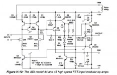
Doug, the guys in my dorm (~1970) were buying the "new" TIP power devices to build essentially the op-amp on steroids style power amp. The pic below (circa 1969 original design) was a modular one that did 100V/usec and if fed some steroids would make a decent PA I'll bet. I'll ask around but unfortunately many involved have passed on.
Scott were these sold as potted/hybrid opamps?
Jan
Scott were these sold as potted/hybrid opamps?
Jan
Yes they were potted into a plastic box with the same lead arrangement (I think) that the JE990 still uses. The PC layout was all done with tape and has squiggly lines running everywhere.
Doug, the guys in my dorm (~1970) were buying the "new" TIP power devices to build essentially the op-amp on steroids style power amp. The pic below (circa 1969 original design) was a modular one that did 100V/usec and if fed some steroids would make a decent PA I'll bet.
Hello Scott
Might well, but as it stands it's just an opamp... R8 will give some of the slew-reducing effect described in APAD6- the current-source base needs to be firmly held at a low impedance to prevent transients feeding through its Cbc and reducing the current.
I'm hoping to expand the 'History of power amps' chapter in APAD6 into maybe a whole book. (if there might be a market for such)
I'd be very interested in tracking down the first power-amp with an LTP input, and the first with a current-mirror. I'm not very familiar with the USA literature so you probably know more about this than I do.
One data point: Daniel Meyer's Tigers That Roar amplifier (Popular Electronics July 1969) had an LTP but no mirror.
Last edited:
One data point: Daniel Meyer's Tigers That Roar amplifier (Popular Electronics July 1969) had an LTP but no mirror.
Nothing yet, Barny Oliver's famous HP PA (1973) also was LTP but no current mirror.
I see what you are looking for, from my perspective the discreet op-amp discloses all the concepts so scaling it up is really not an innovation.
EDIT - This is a funny patent title, "Silent musical instrument with audio power amplifier circuit"
Last edited:
Here's another, somewhat earlier data point for first power amp with a long-tailed pair at the input, from January 1967 issue of Electronics World.
http://www.updatemydynaco.com/HistoricDocuments/JBLTAmp.pdf
I'm sure with more digging, people will turn up even earlier examples.
http://www.updatemydynaco.com/HistoricDocuments/JBLTAmp.pdf
I'm sure with more digging, people will turn up even earlier examples.
Here's another, somewhat earlier data point for first power amp with a long-tailed pair at the input, from January 1967 issue of Electronics World.
http://www.updatemydynaco.com/HistoricDocuments/JBLTAmp.pdf
I'm sure with more digging, people will turn up even earlier examples.
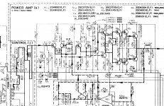
That's not a "blameless". That turned into your typical 1970's Japanese
amplifier. 75' Sansui (below 1).
They kept using the design into the 80's , digital receivers .... (Z5900)
Good design , the two I repaired still worked after 40 years.
Me and another member ported this to a forum design - 20ppm/-120db PSRR.
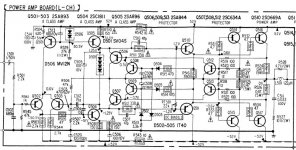
(below 2) is the classic Sony STR series.
Has the LTP in 69' , by the early 70's they added beta enhancement ....
pretty much a modern "blameless" by 73'.
The Japanese were way ahead of anybody in the late 60's - 70's !!
OS
Attachments
In IC design bias sharing is done all the time. I've never seen it done with a base resistor on the mirrors, though. The base current of TR5 would create a drop across R23 which would be undesirable from a matching perspective.
Curious question: What was the original intent with R23?
Tom
Curious question: What was the original intent with R23?
Tom
Here's another, somewhat earlier data point for first power amp with a long-tailed pair at the input, from January 1967 issue of Electronics World.
http://www.updatemydynaco.com/HistoricDocuments/JBLTAmp.pdf
I'm sure with more digging, people will turn up even earlier examples.
I was thinking of this JBL as being on the list of the first amps having a Long Tail Pair input.
Not sure but Marantz may have one at about the same time.
Even less sure, the Gego amplifier in France built amplifiers (1965 ?) which may have had an LTP input. It was aimed to drive very low impedance Orthophase planar cells :
Rétro-forum, le forum de Radiofil, les amateurs de TSF • Afficher le sujet - Qui connais ce type de HP plat équipant des enceintes ?
Système Ge-Go Orthophase - Le forum Audio Vintage
In IC design bias sharing is done all the time. I've never seen it done with a base resistor on the mirrors, though.
But Bob Widlar patented his mirror in 1967. So does that put a date before which no discrete amplifier would have used it?
Here's another, somewhat earlier data point for first power amp with a long-tailed pair at the input, from January 1967 issue of Electronics World.
http://www.updatemydynaco.com/HistoricDocuments/JBLTAmp.pdf
I'm sure with more digging, people will turn up even earlier examples.
Aha, the Locanthi T-circuit. (never thought it looked much like a T, but never mind)
That's a good 1967 data point. Locanthi glosses over the 'differential driver stage' in a sentence, so presumably he did not regard it as anything new.
- Home
- Amplifiers
- Solid State
- The Kiwanuka article in Linear Audio 11: Douglas Self