Normally i use the 96k
My setting at the fistwatt f6 at 1 watt with a signal gen of 1khz.
Used this setting based on the manual of QuatAsylum.
Because i use the load from QuatAsylum I needed to set the input gain setting to -12 db

My setting at the fistwatt f6 at 1 watt with a signal gen of 1khz.
Used this setting based on the manual of QuatAsylum.
Because i use the load from QuatAsylum I needed to set the input gain setting to -12 db
The sample rate can only be changed while acquisitions are stopped. Changing sample rates will result in a
reset of the converters which might cause a slightly pop on the outputs. If you are working on high-gain circuits,
this might manifest as large output changes during sample rate changes. In general, the performance of the
converters is better at lower sample rates. If your measurement task doesn’t require frequencies beyond 20
kHz or so, stick to the 48K sample rate. https://cdn.shopify.com/s/files/1/1631/5609/files/QA40x_Users_Manual.pdf?v=1644257226

Very pleased to hear the update regarding the new edition. The test results are excellent. Hope get a chance to listen to it soon.
In this case you would need power supply that is absolutely stable and low output impedance even at the switching rate you use. Quite a challenge.The power supply used for the test was a 600W switching power supply, which may have larger ripple compared to a typical linear power supply. If the transient response of the switching power supply is suboptimal, it can indeed increase harmonics during high-power output.
I measured the power noise today, found that the power supply I used is very terrible. please see the figure below:In this case you would need power supply that is absolutely stable and low output impedance even at the switching rate you use. Quite a challenge.
Here is the test case, 1kHz, output RMS power 96W.
Here is the power rail measurement.
zooming in
when applying test with 1kHz, the power rail second harmonic (2kHz) is as high as -27.8dBV. comparing to the second harmonic of the AMP output, the Power reject ratio should be larger than 40dB@1kHz.
Unfortunately, I don't have better power supply right now. but believe the THD+N is better than what we measured with better power supply.
thanks @mvs0 to reminder me to consider the power issue.
Attachments
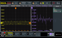
2kHz 96W test is even worst. To be honest, the switch power supply is not that bad, just not good for audio amp.


You could add big (good) capacitors and see if you can reduce the impact of the load?thanks @mvs0 to reminder me to consider the power issue.
How about the PSSR of the amp module - can it be improved? Either you go for a bit wide band noise (SMPS) or the 60/120 Hz hum (linear)...
How can you be sure its is PS limited when you haven't tested with something else?
I think it is the amp intrinsic distortion we see - no? Thats the cost of no global feedback - or?
//
How can you be sure its is PS limited when you haven't tested with something else?
I think it is the amp intrinsic distortion we see - no? Thats the cost of no global feedback - or?
//
I plan to add a LC filter to see if it is better.You could add big (good) capacitors and see if you can reduce the impact of the load?
for the PSSR, obviously, as I said, it is at least 40dB@1kHz. please see the power noise at 2kHz (-27dBV), however, AMP output at 2kHz is -67dBV. if the AMP is distortion free, the PSSR is 40dB. actually, the PSRR is 40dB + distortion contribution.How about the PSSR of the amp module - can it be improved? Either you go for a bit wide band noise (SMPS) or the 60/120 Hz hum (linear)...
How can you be sure its is PS limited when you haven't tested with something else?
I think it is the amp intrinsic distortion we see - no? Thats the cost of no global feedback - or?
if you looked at the distortion measurements I posted couple days ago, you will find that the THD+N distortion is suddenly jump from 0.00x% to 0.0x% when the output power exceeds some Watt (5W). this is not the typic behavior of AMP. So I guess it is from the Power, of course, need further verification.
You have the L already in your PSU output stage, I would also try just C , a big one 🙂 (>=10000uf)I plan to add a LC filter to see if it is better.
Indeed, the LC filter went worse, since I didn't have any larger high voltage caps.You have the L already in your PSU output stage, I would also try just C , a big one 🙂 (>=10000uf)
Also: put it at the amp power connections, not at the PSU.You have the L already in your PSU output stage, I would also try just C , a big one 🙂 (>=10000uf)
Or next time: put a 'sea' of good SMD capacitors on your PCB
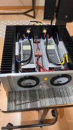
A thrill ran through me as the highly anticipated no-feedback amplifier module finally arrived recently. After a few focused days of assembly, my custom audio amplifier was ready for its maiden voyage. Connecting it to my speakers for the initial listening session left a lasting impression, far surpassing my initial hopes.
The sonic performance immediately stood out. The bass was rich and powerful, delivering a substantial impact. Listening to percussion revealed a wide dynamic range, presented with remarkable speed and absolutely no sense of dragging or delay. The clarity of detail in the lower frequencies was truly exceptional.
Moving to the higher frequencies, the treble was rendered with a pristine clarity and brightness. When I listened to orchestral music, the distinct layers within the music were beautifully presented, creating a strong and immersive sense of being there. Furthermore, the reproduction of vocals was incredibly realistic, capturing subtle nuances and details with impressive accuracy. This amplifier has proven to be truly memorable.
I must also extend my sincere gratitude to Mr. Flmhhh. The no-feedback amplifier design he created is simply outstanding and has brought a new level of enjoyment to my listening experience.
Attachments
Nice work—well done! I’m glad you chose the AMP module, and I hope you’re enjoying the amplifier.I must also extend my sincere gratitude to Mr. Flmhhh. The no-feedback amplifier design he created is simply outstanding and has brought a new level of enjoyment to my listening experience.
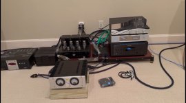
I sent this amplifier to a friend who conducted a comparative test against a Nagra Classic Amplifier under identical conditions. Below is one set of comparison recordings—one from this DIY Class D amp and the other from the Nagra Classic. Both recording files are included in the attached zip file. Please have a listen and share your thoughts.
Attachments
That's a drastic difference in sound between the 2.
I suggest refraining from naming the files to state the obvious, i.e. name the files test_1, test_2.... test_n.... and post again. I'd like to listen again without knowing the source.
I suggest refraining from naming the files to state the obvious, i.e. name the files test_1, test_2.... test_n.... and post again. I'd like to listen again without knowing the source.
- Home
- Amplifiers
- Class D
- The Journey of DIY No-Feedback Class D Amplifier (1) Subtitle: The Motivation and Story Behind It