Have not looked into it yet.
I think it is to do with those low load modes.
Need a high power dummy load to try 100W or so.
But it is common mode in the circuit.
So should not get through to the output.
Patrick
I think it is to do with those low load modes.
Need a high power dummy load to try 100W or so.
But it is common mode in the circuit.
So should not get through to the output.
Patrick
If the SMPS is at the edge of it's load capability you may see re-entrant limiting.
That can be sub-mains frequency.
Jan
That can be sub-mains frequency.
Jan
Thanks for the explanation, Jan.
The Nemesis Quadrige can be put on standby mode by switching off the front end power.
The power MOSFETs will be switched off with 0V Vgs.
So it IS for me interesting to know what the SMPS is doing.
Cheers,
Patrick
The Nemesis Quadrige can be put on standby mode by switching off the front end power.
The power MOSFETs will be switched off with 0V Vgs.
So it IS for me interesting to know what the SMPS is doing.
Cheers,
Patrick
It would be interesting to know the minimum load current of the device and the SMPS output situation in that condition. That would be the normal usage scenario as opposed to no load condition.
Last edited:
The data sheet for the chip gives some info on burst and pulse skipping modes.Thanks for the explanation, Jan.
The Nemesis Quadrige can be put on standby mode by switching off the front end power.
The power MOSFETs will be switched off with 0V Vgs.
So it IS for me interesting to know what the SMPS is doing.
Cheers,
Patrick
I haven't studied it but I've seen such behaviour before.
Not sure it is the case here but probably worthwhile to take a look at it.
Jan

We have a revised PCB which will allow a stack-on daughter board for the bias balancing circuit.
Tested successfully today. 🤓
Patrick
We made 5 pieces of V2 PCB.
Someone else asked for boards before.
So he'll get a pair for Beta test.
But then it seems he is not planning to build soon.
So if someone else is seriously interested and make a promise to build in the next month's, we'll order extra boards to support them.
You can send me a PM.
But only if you are serious about building.
Patrick
Hi everyone,
Some years ago, I built a different version of the NEMESIS amp. It's a 14W class A amp inspired by the "NEMESIS COMPENSE" version. Instead of using N channel MOSFETs, I use N and P MOSFETs (2SK135 / 2SJ50) in a single ended arrangement (no phase splitter or differential stage) with a split primaries push-pull output transformer and bipolar PSU. The transformer is much easier to built and far cheaper (no air gap nor saturation), bandwidth is extended at both ends, ripple is nulled (no need for a regulated PSU). The MOSFETS are triode connected (see my article in "LA REVUE DU SON - 240". The amp is very simple, it uses 4 transistors per channel and is fully DC coupled up to the output trans. Additionally, the bias is optically DC servo assisted.
I think that if bipolar tubes had existed, this sort of circuit would have been in use long ago.
For those interested in the NEMESIS family and don't mind poor English ...
Attachments
Here they are, hope they can be read. A typo : points 3 & 4 are inverted. Source of power MOSFETs (case) are directly connected to 0V which makes wiring and building the amp easier : no insulator needed and possible direct use of the chassis for cooling
Attachments
Last edited:
Jan Didden :
https://www.diyaudio.com/community/threads/hiraga-le-monstre-2024.413301/post-7698907Yes but that one has 4 times the active devices as the original Nemesis 😎
This one is fully balanced and can use lower cost toroidal transformers than the "original".
🙂
Patrick
Patrick
In your articles on the Quadrille you mentioned a "lower cost" toroidal transformer as an alternative. Can you reveal the maker and the model number please, as they are not mentioned.
Regards
Ejam
In your articles on the Quadrille you mentioned a "lower cost" toroidal transformer as an alternative. Can you reveal the maker and the model number please, as they are not mentioned.
Regards
Ejam
Custom made.
You need to find a local manufacturer.
The details already described in the article.
Toroidal transformers cannot be used in the single FET circuit because of the high DC current.
You will then need to order custom EI transformer.
See Jan's article at Linear Audio.
Patrick
You need to find a local manufacturer.
The details already described in the article.
Toroidal transformers cannot be used in the single FET circuit because of the high DC current.
You will then need to order custom EI transformer.
See Jan's article at Linear Audio.
Patrick
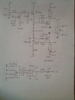
toroïdal trans may be used with the single MOSFET version provided the second primary is connected in the "NEMESIS COMPENSE" style (lower 2SK135 and bias circuitry in the picture attached).
For better efficiency, this nulling circuit may easilly be controlled by kind of a DC servo circuit.
I achieved good results with a 2 x 110 / 2 x 33 V - 330VA toroïdal trans. Complete article here (alas, in French) :
https://www.google.com/imgres?q=nem...d=2ahUKEwjBzsOh9b6GAxXWSKQEHUFHCUAQM3oECF0QAA
Jan Didden was referring to the version with a single active device.
Maybe you have an idea how to use a toroidal transformer for that particular circuit ?
Patrick
Maybe you have an idea how to use a toroidal transformer for that particular circuit ?
Patrick
Yes, I had that in mind. Just wanted to show how to build the "compensation" (not able to find the proper English word) circuit, so I used this 3 trans schematic that shows it. Anyway, it's very easy to use the single MOSFET version with "compensation" in order to use toroidal or push-pull transformers : just make two single MOSFET circuits, connect them to the OPT with the primaries wired in opposite phase. Feed only one MOSFET with the source signal. The second MOSFET is then the current source needed to compensate for the DC current of the first one. This trick can also be used with tube push-pull amps to convert them in single ended mode. You can even imagine a push-pull OPT connected to a triode for signal and a pentode (almost an ideal current source) for DC compensation, say a 300B and a 6L6 for instance, etc. Back to the NEMESIS, as not using the current source circuit for modulation is sort of waste, I imagined the version I posted earlier, where a P channel MOSFET compensates for the DC current AND acts as a push-pull arrangement, without the need of any phase splitter or differential stage as in the QUADRIGE version. With this arrangement and as P and N MOSFETS have somewhat different caracteristics, the pattern of harmonic distorsion keeps very single ended- like.
- Home
- Amplifiers
- Pass Labs
- The Jean Hiraga Nemesis Quadrige