After 3 years of Corona, I got to visit Jan Didden this year, and thought it would be nice to do a small project with him together.
Both he and Nelson had built the Jean Hiraga Nemesis, single-ended version.
https://linearaudio.nl/nemesis-rebuild
https://www.firstwatt.com/pdf/art_arch_nemesis.pdf
But one can find no examples of the push-pull version. There were only 2 posts in the forum mentioning it at all.
https://www.diyaudio.com/community/threads/sit-nemesis.292092/post-5831834
https://www.diyaudio.com/community/threads/what-sounds-better-than-hiraga.280956/post-4485063
And I thought I should do at least one project during my DIY "career" with output transformers.
If only to be able to say "done it before". 🙂
So we did just that.
I have to admit that I am positively surprised.

Patrick
.
Both he and Nelson had built the Jean Hiraga Nemesis, single-ended version.
https://linearaudio.nl/nemesis-rebuild
https://www.firstwatt.com/pdf/art_arch_nemesis.pdf
But one can find no examples of the push-pull version. There were only 2 posts in the forum mentioning it at all.
https://www.diyaudio.com/community/threads/sit-nemesis.292092/post-5831834
https://www.diyaudio.com/community/threads/what-sounds-better-than-hiraga.280956/post-4485063
And I thought I should do at least one project during my DIY "career" with output transformers.
If only to be able to say "done it before". 🙂
So we did just that.
I have to admit that I am positively surprised.
Patrick
.
Attachments

The original article in French can still be found here :
http://www.silicium.org/archive-retronik/revues/?dir=audiophile/1985
With the help of Google Translate, I put together a translated version.
Hopefully without too many mistakes.
Patrick
.
http://www.silicium.org/archive-retronik/revues/?dir=audiophile/1985
With the help of Google Translate, I put together a translated version.
Hopefully without too many mistakes.
Patrick
.
Attachments
And we managed to find a solution for the output transformer.
Very good value for money.

Details in the article, including measurements.
Patrick
Very good value for money.
Details in the article, including measurements.
Patrick
🤓
I would encourage others to build the same.
It is very simple to build, and works first time without issues.
There is no reason why it should not work with equivalents in TO247 packages.
https://www.profusionplc.com/parts/ecf10n20-s
https://www.profusionplc.com/parts/ecx10n20-s
Patrick
I would encourage others to build the same.
It is very simple to build, and works first time without issues.
There is no reason why it should not work with equivalents in TO247 packages.
https://www.profusionplc.com/parts/ecf10n20-s
https://www.profusionplc.com/parts/ecx10n20-s
Patrick
Last edited:
As mentioned earlier, we intend to use a 85V SMPS for supplying the laterals.
We bought a Connex SMPS300RS 80V at a good discount from a EU distributor.

A few quick checks :
Input / outputs are electrically isolated.
Max main output voltage is 84v by voltage adjust.
Aux output is nominal +/-15v, outputs unloaded is measured at -15.87v, +16.40v.
This is too low for the frontend, and most probably too noisy.
So a small separate linear +/-18V supply will be added.
Patrick
We bought a Connex SMPS300RS 80V at a good discount from a EU distributor.
A few quick checks :
Input / outputs are electrically isolated.
Max main output voltage is 84v by voltage adjust.
Aux output is nominal +/-15v, outputs unloaded is measured at -15.87v, +16.40v.
This is too low for the frontend, and most probably too noisy.
So a small separate linear +/-18V supply will be added.
Patrick
The 80V (nominal) output is regulated.
So how regulated is regulated ?
The surprise to me is that rather than seeing switching frequency ripples, we see 50Hz instead.
Maybe it will become less with heavier load.
But we shall add a cap multiplier downstream.

No load.

90mA load.
Patrick
So how regulated is regulated ?
The surprise to me is that rather than seeing switching frequency ripples, we see 50Hz instead.
Maybe it will become less with heavier load.
But we shall add a cap multiplier downstream.
No load.
90mA load.
Patrick
Jan Didden :
https://www.linearaudio.net/nemesis-rebuild
"...because of the output transformer, it was very difficult to get rid of hum that would be coupled from the mains transformer to the output transformer.
A large chassis for physical separation of the transformers as well as painstaking rotation of one with respect to the other would minimize hum.
But I did not find it satisfying.
The solution with the SMPS followed by a simple linear regulator made the amp very quiet."
And I trust Jan.
Someone who has actually built the amplifier.
Cheers,
Patrick
Last edited:
A different amplifier (SE), a probably different SMPS, a different person (that you trust which is good). Apart from those details a friendly reply to a question that was not asked 🙂
Last edited:
A very nice approach.
I see the newer laterals ECF10N20 have the same pinout as the older 2SK135/2SK175 (I have several matched): also 1. GATE 2. DRAIN 3 SOURCE ! Great news, as this board would fit. available??
A have a bifilar wound toroid from Métalimphy: 110/110V : 9/9V @ 200Watt so a much higher winding ratio, 1:11. In series out, 1:6 instead of 1:2. That would set me back into the area of requiting higher voltage outputs (high voltage SITs...) , so it is non-fit for purpose? I used that output for a PP-EL34 cathode coupled output sec// = 1:11, and it was marvelous, >10Hz - something like >60KHz and no overshoot. In series its 1:6, so about 250Ω primary. Not quite within reach of Hiraga's 64Ω. I saw someone damp the primary to a lower impedance with 100Ω parallel but that scares me.
ps. The 'compensated' version of the Némesis that Jean Hiraga published [when??] is interesting too as - if I understand correctly - it has a same DC standing current from the second transistor used as CCS? So the amplifier stays single ended. The very precise balancing of currents in a toroid is prime issue, as some designers have mentioned. But with a >500H gyrator/echoke one can use the same current passing through the core twice, I think. And hence force the same average current. But I deviate.
I see the newer laterals ECF10N20 have the same pinout as the older 2SK135/2SK175 (I have several matched): also 1. GATE 2. DRAIN 3 SOURCE ! Great news, as this board would fit. available??
The new toroid (29+29v)+(29+29v) : 4x29V//, so 1:2? 32Ω primary?this will mean that the secondary would only have to be specified as 29V for 8ohm and 20V for 4ohm.
A have a bifilar wound toroid from Métalimphy: 110/110V : 9/9V @ 200Watt so a much higher winding ratio, 1:11. In series out, 1:6 instead of 1:2. That would set me back into the area of requiting higher voltage outputs (high voltage SITs...) , so it is non-fit for purpose? I used that output for a PP-EL34 cathode coupled output sec// = 1:11, and it was marvelous, >10Hz - something like >60KHz and no overshoot. In series its 1:6, so about 250Ω primary. Not quite within reach of Hiraga's 64Ω. I saw someone damp the primary to a lower impedance with 100Ω parallel but that scares me.
ps. The 'compensated' version of the Némesis that Jean Hiraga published [when??] is interesting too as - if I understand correctly - it has a same DC standing current from the second transistor used as CCS? So the amplifier stays single ended. The very precise balancing of currents in a toroid is prime issue, as some designers have mentioned. But with a >500H gyrator/echoke one can use the same current passing through the core twice, I think. And hence force the same average current. But I deviate.
As explained in the article, the toroidal transformer is 58V+58V : 29V.
So it is 2+2:1, or 4-CT : 1, same ratio as Jean Hiraga's.
Also explained in the article,
the reason why we did not specify 110V+110V : 58V is that the windings would not have the low resistance and high current rating as that above.
110V + 110V : 18V would be 12-CT : 1, which will need much higher voltages at the primary, something like 240V.
And then it is not the Nemesis Quadrige anymore.
We have a revised PCB which will allow a stack-on daughter board for the bias balancing circuit.
We shall test that first before making it available.
In our case, because of careful matching and thermal management, we could not measure any differential bias current.
So we shall not be using bias balancing. There is no need to, in our case.
Patrick
The surprise to me is that rather than seeing switching frequency ripples, we see 50Hz instead.
I think we see thirty Hertz, not fifty ?
_
Attachments
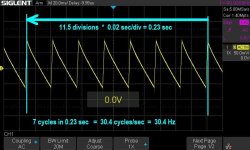
I'm surprised an SMPS outputs a very low frequency ripple that's not mains related. 30 Hz ?? It isn't even a subharmonic of 50 Hz.
- Home
- Amplifiers
- Pass Labs
- The Jean Hiraga Nemesis Quadrige