guys 🙂 i have an active crossover i use for the subs im recycling for this build - so there will be no crossover costs or build for this project 😀 
i have tried these drivers in bandpass (4th order and 6th, isobaric and not) and i cant really say i get a response im happy with. i have seen bandpass designs with this same driver, but when i plot the same design i do not like the sims. i suspect these drivers are harder to design in that setup for me 😀
i have tried these drivers in bandpass (4th order and 6th, isobaric and not) and i cant really say i get a response im happy with. i have seen bandpass designs with this same driver, but when i plot the same design i do not like the sims. i suspect these drivers are harder to design in that setup for me 😀
after checking those configurations i really do not know how to design one of those i dont think winsid does those enclosure?!?.
would be interesting to sim
would be interesting to sim
mh-audio calculation page: TQWP
Hi there b: Google-up: mh-audio and look down the calculation page for "TQWP".
....regards, Michael
... I really do not know how to design one of those i dont think winsid does those enclosure. would be interesting to sim
Hi there b: Google-up: mh-audio and look down the calculation page for "TQWP".
....regards, Michael
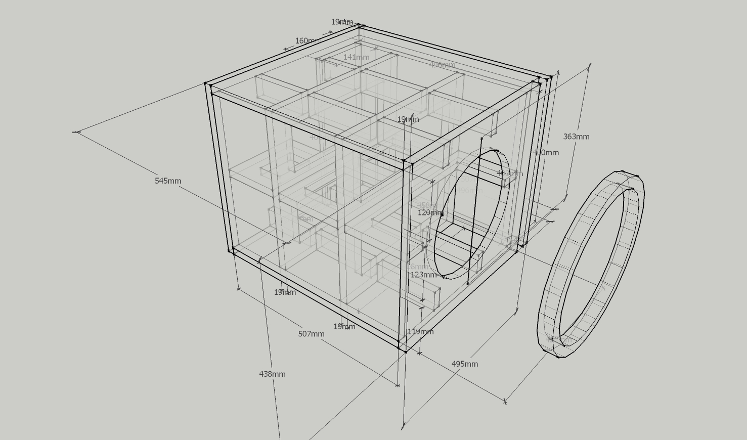
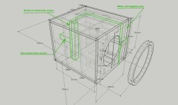
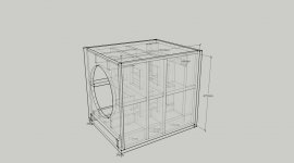
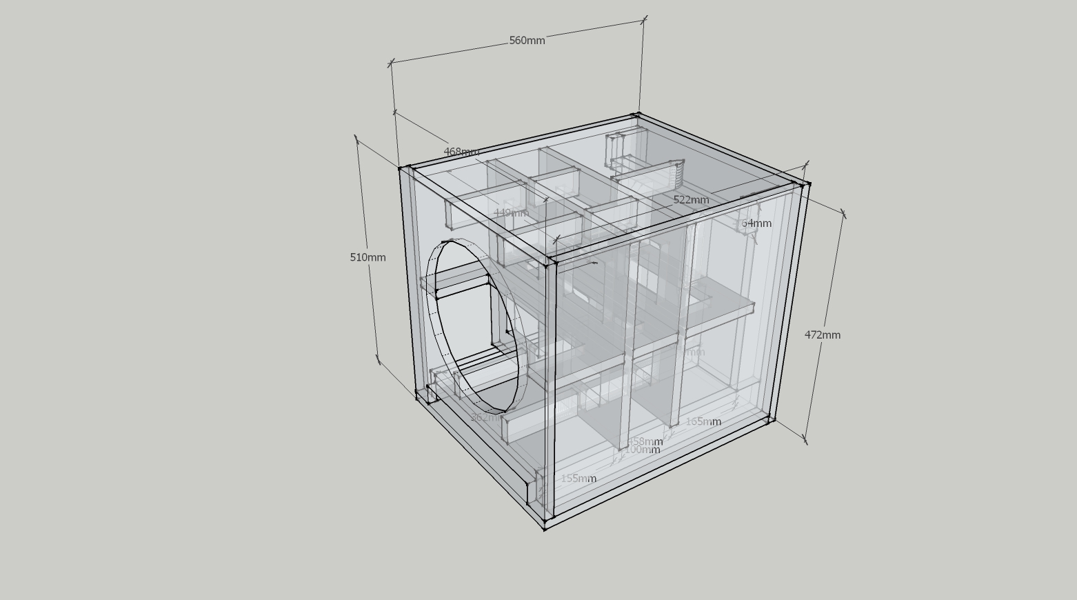
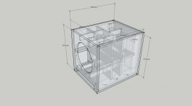
im finishing the final design of the isobaric subwoofers. instead of one big sub im building 2 half the size.
final design.
the ring is for separating the 2 woofers.
sorry for the random numbers in the sketch, i forgot to clean out some old measures that arent relevant.
the ring is for separating the 2 woofers.
sorry for the random numbers in the sketch, i forgot to clean out some old measures that arent relevant.
Attachments
Last edited:
Hi butterwitz,
Your Sketchup skills are remarkable.
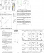
Just my 2 cents on this design: I guess, that the narrow slot on the right hand side of the enclosure front is the port. That's a very flat, high aspect ratio opening. I'll attach two general analysis done by bjorno on this subject, the 1st one is on port correction, and the 2nd one is on port flares/nozzle ports.
Also, here is a link to Flare-it, a port/flare calculator:
Port Flares - Evaluation of noise
You are going to put a lot of work into this box, so it may be a good idea to take another look at the port design. I feel that the port as currently drawn might choke off at high SPL levels.
Regards,
Your Sketchup skills are remarkable.
Just my 2 cents on this design: I guess, that the narrow slot on the right hand side of the enclosure front is the port. That's a very flat, high aspect ratio opening. I'll attach two general analysis done by bjorno on this subject, the 1st one is on port correction, and the 2nd one is on port flares/nozzle ports.
Also, here is a link to Flare-it, a port/flare calculator:
Port Flares - Evaluation of noise
You are going to put a lot of work into this box, so it may be a good idea to take another look at the port design. I feel that the port as currently drawn might choke off at high SPL levels.
Regards,
Attachments

yeah man, im VERY thankful for your input 🙂 because you adresed this exactly in the last moment 😀 i think you are rigth but i lack the skill and knowledge to make the design much better i think 🙁 - BUT i WILL give it a try 😀
i did see those papers by bjorno before - but i do admit i could not make sense out of them. i guess my main problem is i am not an engineer 🙁 i will have a deeper look into the papers today.
the slot vent in this design i calculated to get 0.05 mach airspeed using win-isd.
i have a rounding off router bit i thought of using later one on the slot outlet and part of the inlet. but first i want to make sure i get this design better 🙂
the slot in this design is 3 x 40 cm - which i realize is a 1 to 13 ratio or something..
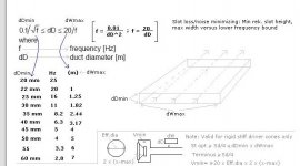
if im rigth this the information relevant to my build 🙂 the diagram shows same values as in the other paper relating to port height (H in mm) and port width (W in m) - but this to me makes little sense - i read it as the maximum width for 30 mm (3cm) is 1.82m - thats like 6 foot wide 🙂
i must read this wrong! 😀
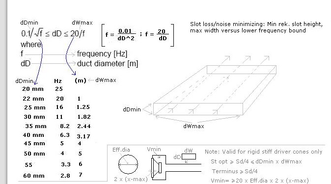
on the other paper it clearly states its M like in meters for the width - so i have to say i honestly do not get this - since a 1.82m is 182 cm (6 foot!) - and that just cant be? hehe it sounds too wide!
if so - it means my ratio of the heigth to width should be ok - but then again if i do not understand this correctly i will fail miserably 🙁
i someone could confirm this it would be awesome. 🙂
i must read this wrong! 😀
on the other paper it clearly states its M like in meters for the width - so i have to say i honestly do not get this - since a 1.82m is 182 cm (6 foot!) - and that just cant be? hehe it sounds too wide!
if so - it means my ratio of the heigth to width should be ok - but then again if i do not understand this correctly i will fail miserably 🙁
i someone could confirm this it would be awesome. 🙂
Attachments
Last edited:
Hi butterwitz,
I think you are reading it correctly. I was more thinking about the length correction, same page, upper left hand corner, and I'm like you: some of that data does not quite compute with me (like the table you quoted). I think this table applies more to the general flow characteristics of a duct then to the inlet/exit conditions.
I did not catch, that your port is actually 30mm high, when looking at it it looked more like 19mm, but now I see that's just an intermediate design stage front baffle overlapping the port (?). Anyway, the basic answer is to increase the height of the port, which will mean you'll have to increase the length, and maybe the size of the box to make up for the volume losses. I would also recommend to support the center of the port with a brace, as otherwise the unsupported outside boards are a bit on the wide side. I would add an edge support at the inlet, and round off all corners of the port inlet/exit.
Anyway, good luck with your build.
Regards,
Attachments
🙂 you are right about the port braces. i already prepared ones for my tarkus builds slotted ports, and i thought of doing the same with these. i also did plan to do the rounding off on exact same spots as you suggested - i even got a router bit for it today 😀
the thought i had was to try the subs out first and if i hear chuffing, slide the divider (cut to exact heigth for snug fit) in from the front and secure it with a bit of superglue. but i might actually do it now as part of the building process.
maybe not the best design method 😀 but the dividers i thought of are long enough to go along most of the length of the vent and effectively cuts the vents into 2 slots with much lower width to height ratio (1 to 6)
in the image of the design the slot looks thinner i guess due to the perspective.
i have the bad luck (due to wifes restrictments) to have restricted space for the subwoofers, and the actual width of these (i will build 2) can not be changed however i can maybe make them a little taller maybe.
im now looking at the vent in winisd. i can not increase the height too drastically of the vent - the length goes way over what is reasonably possible - if i even increase the width with 1cm (4cm x 40cm port) the length will get so long it will fully cover 2 walls of the enclosure.
i think maximum increase i could do is maximum around 1 cm more - if not the port resonance starts creeping down too close 🙁 with 4x40cm slot win isd calculates the 1st port resonance to 193 hz.
Last edited:
Just ran across this thread - looks a lot like something I designed in this thread (the XKi dual driver 6th order band pass sub):
http://www.diyaudio.com/forums/subwoofers/274658-high-spl-bass-l7-12s-sq.html
http://www.diyaudio.com/forums/atta...-sq-alpine_sws_10d4_dual_beatstreet_dwg_1.pdf
http://www.diyaudio.com/forums/subwoofers/274658-high-spl-bass-l7-12s-sq.html
http://www.diyaudio.com/forums/atta...-sq-alpine_sws_10d4_dual_beatstreet_dwg_1.pdf
hm.. i think i will re design the enclosure using a 4.5cm x 36.2cm vent - this would be a 1 to 8 ratio - withing the recomended 1to4 - 1to9
this new vent would be 90.7cm long port. i will really have to have a good look at how i can fit that into the box - it will cover 2 walls and part of one wall unless i can think of a neat solution.
ill be back 🙂
this new vent would be 90.7cm long port. i will really have to have a good look at how i can fit that into the box - it will cover 2 walls and part of one wall unless i can think of a neat solution.
ill be back 🙂
Just ran across this thread - looks a lot like something I designed in this thread (the XKi dual driver 6th order band pass sub):
http://www.diyaudio.com/forums/subwoofers/274658-high-spl-bass-l7-12s-sq.html
http://www.diyaudio.com/forums/atta...-sq-alpine_sws_10d4_dual_beatstreet_dwg_1.pdf
wow thats awesome! 🙂 well i finally drifted away from the double sub enclousre to 2 separate enclosures. it will be easier to handle 😀
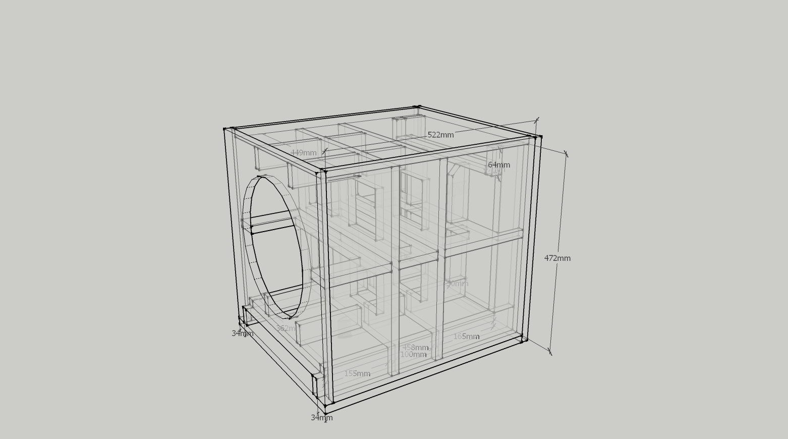
ok this is the new sketch.. 1:8 ratio on vent. vent is 90cm long!
tomorrow i will adjust the volume to fit with the bracing etc, i will probably do a few smaller changes.
had to turn the subs around and put the vent on the floor as in the original plans i had.
im not entirelly sure i like this design, maybe tomorrow i will find a final thought. i have more or less decided to wait with ordering the material until next week.. so i will have time to get a decision.
the dividers/braces inside the vent arent showing too well. they are more or less aerodynamically shaped, like looking at a canoe from above 🙂 also as before all edges of the vent inlet and exit will get rounded off.
vent dimensions are 4,5cm height x 36,2 cm width and 90,7cm length
the separating ring for the clam mounted woofers is still part of the design, but not in the pic
Attachments
Last edited:
well i did check the volumes now and i actually did reach the target volume within 0,5 liter so i only added one small brace more in the vent inlet area to compensate for this.
now this design is not too bad imho, but my only problem is i eally dont know where to put the connectors now when the whole backside is covered by the vent hehe 😀 on top of these subs there will be a rack furniture i made, so i will check if i can have the connectors for the cables on the top side, close to the vent inlet.
the calculated PEAK airspeed in the vent will be below 13m/s or 0.04 mach. first port resonance will be at 189Hz
again i will add, the outlets and inlets of the vent will get rounded off with a router bit. the separator ring for the clam mount is not included in the picture.
Attachments
Last edited:
- Status
- Not open for further replies.
- Home
- Loudspeakers
- Subwoofers
- the isocube project