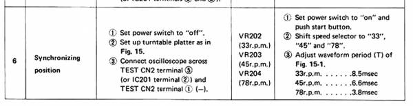
The biggest improvement you can make after changing C146/7/8 is to align the PLL as page 10/11 No.6
I've read these posts.
It's okay...but the benefits will be minimal ...if any.
From the moment it starts to wear, a bit more of the ball "sees" the trust plate and after a point the wear is minimal...it takes years of continuous operation to wear it out.
The problem with these inverted bearings is that they run essentially dry.
At the moment i am working on a solution that will make it immersed in oil.
That will really make a difference in maintenance.
The biggest improvement you can make after changing C146/7/8 is to align the PLL as page 10/11 No.6
These guys?
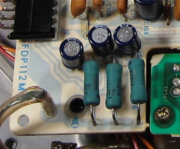
What about the series resistors? Would matching them down to a RCH make any difference?
And this?
Noted. Thanks!!
Well...i have opened three of them (SP-10 and SP-10MKII) and they looked bone dry to me.
A minimum of oil was "felt" more than seen on the spindle.
Maybe the oil used was too thin and "evaporated"?
And the bushings are not the type that hold oil in them too.
Maybe the ones i saw were poorly maintained...
In a no compromise rebuilt it's advised to check wear to find if you're after new bushings.
The problem with these inverted bearings is that they run essentially dry.
.
Inverted ????????
Dave
These guys? Yes
What about the series resistors? Would matching them down to a RCH make any difference? No
And this? Yes
Noted. Thanks!! You are welcome ![/QUOTE]
Inverted ????????
Yes, when the table is upside-down.
The real challenge of that attitude is tracking force...
The PCB caps arrived. 🙂
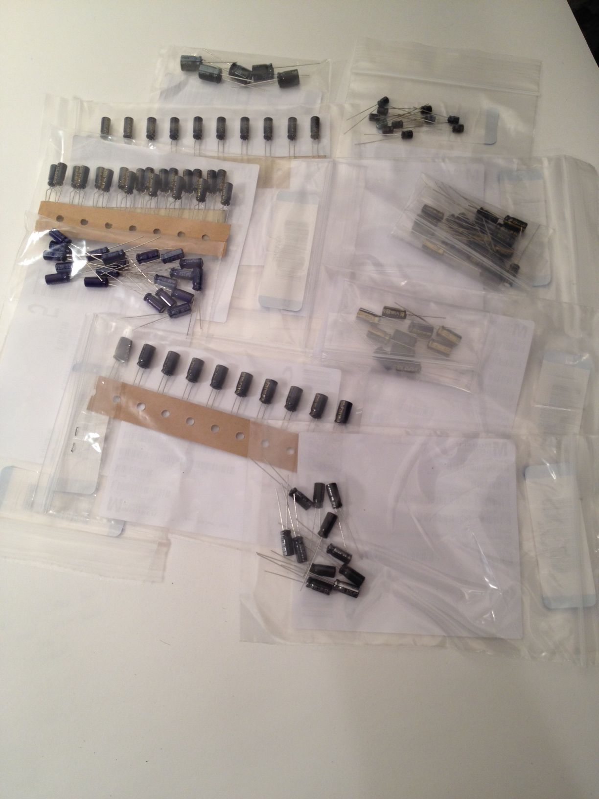
All Panasonic, naturally.
(Of note, Panasonic is discontinuing all through-hole capacitors. So if you want some, order now...)
All Panasonic, naturally.
(Of note, Panasonic is discontinuing all through-hole capacitors. So if you want some, order now...)
I started the re-cap procedure, it's all very straightforward. There are some things that need repair on the PCB, I.E., the fixing of poor repairs... But nothing major.
More photos as I progress.

More photos as I progress.
Last edited:
I've completed the re-cap on one of the boards (save for one cap I didn't realize was a bi-polar electrolytic, so I need to order a few of those...)
When I get into the remainder of the 2nd board I'll grab some photos.
It's a straightforward process, and although the PCB are thin with thin copper, it's made up for by there being silkscreen on both sides of a single-layer board. 🙂
When I get into the remainder of the 2nd board I'll grab some photos.
It's a straightforward process, and although the PCB are thin with thin copper, it's made up for by there being silkscreen on both sides of a single-layer board. 🙂

So once opening the table up and getting to the solder side of the PCB I find one things that are less than optimal... This being the worst offender. There was power resistor replaced on the board, and on this table it was made by somebody badly connecting 2 resistors in series. When they did this the traces lifted and this mess was made.

Here's the new resistor, with bends in the leads to let things heat up without stressing the PCB any more. (In this photo it looks like the bend blocks the pot - it's only camera angle, and the pot is easily accessible.)

Luckily there was a few unused holes in the PCB where it could attach, and the lift trace could be left completely alone.

Ok, this one is all my fault... It's a very fragile board, 31yr old, with surprisingly thin copper. Luckily there is a few places where I could re-attach the lead and make the circuit.

The board with beautiful new caps.

Dead soldiers

With the PCB off I can see the production date of the motor. I was in 3rd grade of elementary school that day. 🙂
Last edited:
Hi. For your power resistor installation you have to realized that there is still risk of applying stress to the PCB traces. The proper way to mount an heavy part, such as this power resistor, is to bend the part leads as shown. Then mount the part in such a way that the lead bend is touching the top of the board. This way the part cannot push on the bottom PCB trace, and the part cannot pull out on the pcb because it is soldered from the bottom. Also if it was me I would put pieces of heatshrink on the long section of exposed leads to prevent shorting if the part is bent by accident.
If you look at the old TV HV/Drive PCB you'll see that they always mount power parts this way. Just my two cents.
If you look at the old TV HV/Drive PCB you'll see that they always mount power parts this way. Just my two cents.
Attachments

Last edited:
NICE, I can't wait to see those things.
Everything looks like it's going well for such old gear.
Everything looks like it's going well for such old gear.
- Home
- Source & Line
- Analogue Source
- The Incredible Technics SP-10 Thread