@stockholmstar
For a few Swedish crowns that the capacitors cost, I would have no doubts for their complete replacement; at the limit it is possible to avoid replacing the 1000 uF 80V one of the power supply.
For a few Swedish crowns that the capacitors cost, I would have no doubts for their complete replacement; at the limit it is possible to avoid replacing the 1000 uF 80V one of the power supply.
I'll refer you to this post: I'll just refer you to here: The Incredible Technics SP-10 Thread.
Visual inspection can weed out the obviously bad, but just because a cap looks fine doesn't mean it's good.
JP, I have sent you email and private messages here... are you getting them?
Not sure what is going on?
Hey Rick - the messaging system here has always been hit and miss for me. Just slammed with SP-10's and tonearms. I'll look for your e-mail.
Well, I have a problem I can't solve in this damn mk2A; adjustments have been made and all speeds 33-45 78 rpm. fall as per service manual.
But the oscilloscope detects a waveform soiled by some disturbance also detected with the stethoscope.
At 33 rpm you don't hear anything but at 45 rpm you start to feel the noise and at 78 rpm. is more amplified (always listening with the stethoscope)
This disturbance is injected into the engine which I then detect but not having an identical forklift next to me to do the tests I cannot move at randomly.
Last edited:
First have you checked for any mechanical issues.
The damping material under the platter has a tendency to fall out. If it was intermittently rubbing it would cause the PLL to correct.
Remove the brake cover and check for signs of mechanical binding. Remove the motor rotor and do the same.
The damping material under the platter has a tendency to fall out. If it was intermittently rubbing it would cause the PLL to correct.
Remove the brake cover and check for signs of mechanical binding. Remove the motor rotor and do the same.
Well, I have a problem I can't solve in this damn mk2A; adjustments have been made and all speeds 33-45 78 rpm. fall as per service manual.
But the oscilloscope detects a waveform soiled by some disturbance also detected with the stethoscope.
At 33 rpm you don't hear anything but at 45 rpm you start to feel the noise and at 78 rpm. is more amplified (always listening with the stethoscope)
This disturbance is injected into the engine which I then detect but not having an identical forklift next to me to do the tests I cannot move at randomly.
More detail please - picture of the scope trace, and where exactly you're measuring would help.
MK2As are a bit more involved for calibration and I've seen them suffer some interesting ailments, such as FG signal problems. If it's misbehaving the best way to check FG signal integrity is to disconnect the mechanical brake and spin the platter by hand with your scope on AN660 pin 16 or TESTCN2 pin 7. If the motor seems like it's 'fighting itself' then offset voltage calibration would be high on my list.
@warrjon @jp
many thanks for your assistance, but maybe i solved it.
I will soon explain how. 🙂
many thanks for your assistance, but maybe i solved it.
I will soon explain how. 🙂
Hi ,
I bought a fantastic condition sp10 mk2 last week,it came with a running spare sp10 which is in poor cosmetic condition. It differs to the good one by having a red LED on the start/stop button and a sticker on the bottom cover has an X after SP10 mk2.
Does anyone have any info on this model please?


I bought a fantastic condition sp10 mk2 last week,it came with a running spare sp10 which is in poor cosmetic condition. It differs to the good one by having a red LED on the start/stop button and a sticker on the bottom cover has an X after SP10 mk2.
Does anyone have any info on this model please?
@jamie123
I have never in my life seen a SP10 MK2 with a led on the start-stop button; it could be a DIY modification rather than Matsushita.
I have never in my life seen a SP10 MK2 with a led on the start-stop button; it could be a DIY modification rather than Matsushita.
@jamie123
I have never in my life seen a SP10 MK2 with a led on the start-stop button; it could be a DIY modification rather than Matsushita.
I suspect that it is indeed a 'factory' mod - the fact that it carries the 'X' designator indicates that it is not a normal product. It was probably built to order for a professional user
It would be very interesting to see the Power Supply and its innards - also the main boards under the top-plate. These will be very much more informative.
ok that sounds intriguing,it didn't come with a power supply but the normal sp10 psu works with it. i'll take the bottom cover off later and post some photos.
I suspect that it is indeed a 'factory' mod - the fact that it carries the 'X' designator indicates that it is not a normal product. It was probably built to order for a professional user
It would be very interesting to see the Power Supply and its innards - also the main boards under the top-plate. These will be very much more informative.
everything is possible but I would not be 100% sure, we would need to find some owner who has seen it met or has owned it.
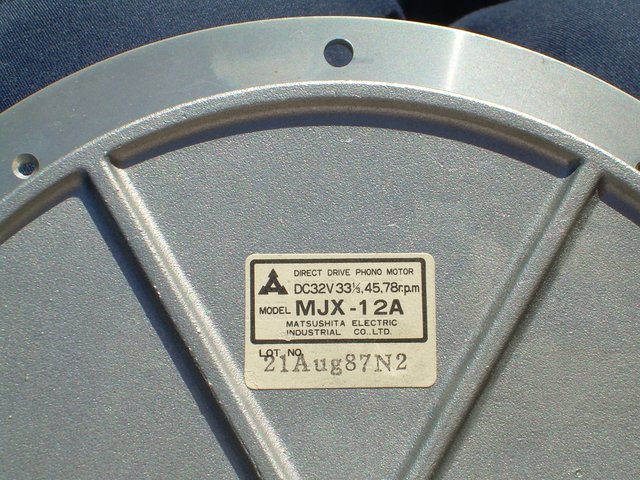
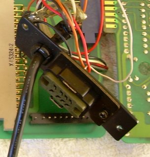
My mk2 that does not have the X in the serial number, had a button on the top of the turntable next to the Technics badge which I removed and grouted the hole before repainting it completely and an connector like this one at the output which I then replaced with the connector of series .... the motor and consequently the whole turntable was dated 21st August 1987 so I suppose the turntable was assembled and sold after that date in the same year (1987) on commission although the mk2 had not been in production for years.
My turntable this is not a BBC version.
Last edited:
@Pitrus
Your pictures do not open!
As the power supply was missing it is also possible that the unit was part of an installation which used a single suitable PS to run a few TTs. This may well have been, for example, an outside broadcast vehicle or even a hospital broadcast station.
Your pictures do not open!
As the power supply was missing it is also possible that the unit was part of an installation which used a single suitable PS to run a few TTs. This may well have been, for example, an outside broadcast vehicle or even a hospital broadcast station.
@Pitrus
Your pictures do not open!
As the power supply was missing it is also possible that the unit was part of an installation which used a single suitable PS to run a few TTs. This may well have been, for example, an outside broadcast vehicle or even a hospital broadcast station.
Really? The intervention of other forumers would be enough to confirm or deny about my photos whether they are seen or not ... I followed the instructions to insert the photos, nothing else.
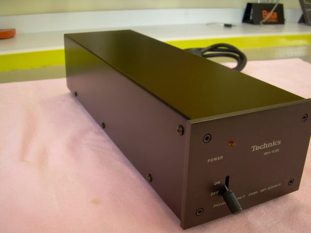
The supplied power supply was a normal SH10E.
Last edited:
- Home
- Source & Line
- Analogue Source
- The Incredible Technics SP-10 Thread