Besides that, there are now many drivers with ventilation holes below the spider (exposed voice coil) or even elevated spider. Those would have the same problem.how do small particles of steel get into the enclosure?
(Attached cheap peerless sds woofer)
Attachments

Clock radio project. Interior screws were second sourced. The second source did not hard the screws. They would chip slightly from the screw driving bit. Better than 40% were failing. The failure was traced to small steel filings that were coming from the screws. It can and does happen. I agree for you guys in home audio, little chance unless you are epically careless. In manufacturing it is not exactly unheard of. I didn't work on that project but I know the factory owner well.Besides that, there are now many drivers with ventilation holes below the spider (exposed voice coil) or even elevated spider. Those would have the same problem.
(Attached cheap peerless sds woofer)
Any high quality loudspeaker these days, has a nice and open spider.Besides that, there are now many drivers with ventilation holes below the spider (exposed voice coil) or even elevated spider. Those would have the same problem.
(Attached cheap peerless sds woofer)
Some also a vent at the back, vents at the VC or a vent just above the VC in the cone.
For a proper excursion limiting device it is important to emulate the transfer-function of the excursion in "real-time".Keep in mind that compressors also limit the voltage, NOT the excursion.
So you better make sure you reach cone excursion limits well before voltage/power limits with a big margin.
If there is a fixed gain (i.e. no user intervention possible) for the whole chain from DSP to amp output then there is a chance to emulate excursion by a filter function in order to control the limiter. For a closed box this would mean a 2nd order lowpass and for a reflex box a 2nd order lowpass and a 2nd order notch filter. If the gain is not fixed the voltage would have to be taken from the amp output which does of course leave the possibility for unwanted user intervention.*
The limiter itself can be a simple "VCA" - limiting everything (which is not very elegant) or one goes for a frequency dependant limiter. Two possibilities for the latter are either the use of a crossover and selective limiting of the lower branch or the use of a steerable highpass (I intentionally left out the ELF circuit). I would say for a DSP implementation the former is easier to achieve.
Regards
Charles
* Keep in mind that it is almost impossible to make any really foolproof system because the fool are much too inventive.
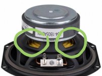
SDS woofer shown in post # 181
Could be considered cheap...I guess.
Has vented spider and bumped back plate.
And large mounting ring.
So actually appears to be rather good.
Going to cast frame would not be much of difference.
Since a lot of the magic of cast frame is heavier mounting ring.
Easily reproduced as shown by making the stamped frame
with a larger mounting area.
They Figured this stuff out way way back in the 80's
Seems pretty well designed actually.
Midrange duty would be rather good thermally.
Since spider is vented. The bumped back plate is likely
to increase linear travel for bass.
Not always a concern for midrange.
But venting the spider likely also for bass ( more heat)
can be beneficial.
As noted in the OP
Basically yes.
Once your on a high pass filter for midrange duty
Linear excursion is non issue.
You will exceed the thermal rating before you hit xmax.
Many " small " drivers
these days are designed for more wideband use.
AKA are designed to make " more bass"
So if considering drivers for midrange duty only.
You might be more worried about sensitivity.
Since a driver designed for wider bandwidth.
Again AKA " more bass"
has likely made some tradeoffs in sensitivity
to make more bass. Also likewise might have higher
inductance for bass duty ( larger voice coil )
so might not have as much ideal detail up top.
Or cone design with more breakup.
Big clue is usually Sensitivity and Fs. Among many others
A speaker with 65 to 80 Hz Fs might not be too good
for bass. But midrange duty, highly likely it has smaller coil ( Le) / less cone weight
and be much more suited for midrange.
You dont need massive magnets for mids.
So even possibly Qts is high since they dont throw
huge magnets at it and suspension could be stiffer for sensitivity.
I've worked with THAT compressor IC's for years. They do a pretty good job for analog compressors.For a proper excursion limiting device it is important to emulate the transfer-function of the excursion in "real-time".
If there is a fixed gain (i.e. no user intervention possible) for the whole chain from DSP to amp output then there is a chance to emulate excursion by a filter function in order to control the limiter. For a closed box this would mean a 2nd order lowpass and for a reflex box a 2nd order lowpass and a 2nd order notch filter. If the gain is not fixed the voltage would have to be taken from the amp output which does of course leave the possibility for unwanted user intervention.*
The limiter itself can be a simple "VCA" - limiting everything (which is not very elegant) or one goes for a frequency dependant limiter. Two possibilities for the latter are either the use of a crossover and selective limiting of the lower branch or the use of a steerable highpass (I intentionally left out the ELF circuit). I would say for a DSP implementation the former is easier to achieve.
Regards
Charles
* Keep in mind that it is almost impossible to make any really foolproof system because the fool are much too inventive.
Although I consider this as offtopic, we can take a brief sidestep for a little bit.
The easy way of doing this, is to have a low pass filter in front of the trigger of the compressor and design the low-end on such a way that it's excursion limited not power/voltage limited.
You want at least 3dB of headroom here. Ideally more.
Or like you said, use a certain real-time model instead.
We can either choice to let the compressor control the entire full bandwidth signal or just the low-end.
When you just do the low end it will skew the overall sound. Which can sound rather weird sometimes.
Although, since we're talking about a last resort limiter in this case. That might not be an issue.
With parallel and nested filter blocks and some more trickery we can even do this with just one driver.
Like I mentioned before, it's only a lot of hassle and potentially a serious point of failure for something that doesn't give a lot of audible trouble in the first place.
Even with very sophisticated models, it's extremely difficult to predict the real world response at a given time.
Best other option would be a feedback solution with a bunch of sensors.
These can even be just optical limiting switches.
But again, it quickly becomes extremely complex.
At that point you might as well build a feedforward model to compensate the distortion.
This brings me back to a point that's being skipped over.Once your on a high pass filter for midrange duty
Linear excursion is non issue.
As far as I can tell, if there is no excursion anymore (or very little), we are just left with HD distortion (THD) and a bit of current modulation?
Since we're focusing on mid-range (> 100-150Hz) only anyway, we can either optimize a driver or find a driver with a higher efficiency.
Which is highly proportional to the Fs.
Higher efficiency means less current needed, means less current modulation.
yes. sorry 1995That's very cryptic, lol
I think you mean this one?
https://secure.aes.org/forum/pubs/conventions/?elib=7684
That is why midranges exist, isn't it? In a normal bass-mid overhung built woofer lots of current (you'd say 2/3, with normal voice coil heights and gap heights) flows uselessly. And creates problems. If one doesn't need the excursion, a short voice coil is just a good idea. Hell, you might even skip the copper caps and rings...Since we're focusing on mid-range (> 100-150Hz) only anyway, we can either optimize a driver or find a driver with a higher efficiency.
Which is highly proportional to the Fs.
@lrisbo I do have a question about Sd(x)
So my first initial thought, was that it would have a major impact on Vas as well, since this is proportional to Sd².
However, I realized that this is not the case.
To make things a bit easier for us, here a visualization from that paper;

We get a graph where the Sd is smaller going outwards and bigger going inwards on respectively to max and min of a (single) sine wave.
This is fundamentally different compared to non-linearities like BL(x) or Cms(x), where the graph is symmetrical.
Aka; dip (or rises) on both sides.
Or in other words, the values will change equally on both sides of the since wave.
Meaning that the actual value has changed at these greater cone excursion, since the actual value is the average between (+x_max + -x_max) / 2
I think Klippel calls this the effective value if I am not mistaken?
However in this case, the value of Sd won't change, since (+x_max + -x_max) / 2 = equal to the rest position of the Sd (more or less)
I guess the only place were modulation can occur in this case, is when we are at the maximum of the cycle and at the same time have some other stuff going on.
But I have a hard time picturing that as modulation, since only half a cycle later this is totally gone again?
So my first initial thought, was that it would have a major impact on Vas as well, since this is proportional to Sd².
However, I realized that this is not the case.
To make things a bit easier for us, here a visualization from that paper;
We get a graph where the Sd is smaller going outwards and bigger going inwards on respectively to max and min of a (single) sine wave.
This is fundamentally different compared to non-linearities like BL(x) or Cms(x), where the graph is symmetrical.
Aka; dip (or rises) on both sides.
Or in other words, the values will change equally on both sides of the since wave.
Meaning that the actual value has changed at these greater cone excursion, since the actual value is the average between (+x_max + -x_max) / 2
I think Klippel calls this the effective value if I am not mistaken?
However in this case, the value of Sd won't change, since (+x_max + -x_max) / 2 = equal to the rest position of the Sd (more or less)
I guess the only place were modulation can occur in this case, is when we are at the maximum of the cycle and at the same time have some other stuff going on.
But I have a hard time picturing that as modulation, since only half a cycle later this is totally gone again?
Actually, I think a underhung design is even a much better idea 🙂That is why midranges exist, isn't it? In a normal bass-mid overhung built woofer lots of current (you'd say 2/3, with normal voice coil heights and gap heights) flows uselessly. And creates problems. If one doesn't need the excursion, a short voice coil is just a good idea. Hell, you might even skip the copper caps and rings...
Demodulation rings are also beneficial for current modulation, so please keep them 😉
But they can be obviously a lot smaller and shorter.
But yeah in a mid-woofer that has to do it all, it seems there is a big penalty because of the low-end, since the mid-range has to suffer from basically all the things.
Current, power, excursion, lower sensitivity = even more power and current.
Maybe you only add some DC to the acoustic signal 😊 oh no, it's not that either.But I have a hard time picturing that as modulation, since only half a cycle later this is totally gone again?
Sd(x) needs to be constant for linear operation. The average value just tells you what the gain of the fundamental is.@lrisbo I do have a question about Sd(x)
So my first initial thought, was that it would have a major impact on Vas as well, since this is proportional to Sd².
However, I realized that this is not the case.
To make things a bit easier for us, here a visualization from that paper;
View attachment 1321959
We get a graph where the Sd is smaller going outwards and bigger going inwards on respectively to max and min of a (single) sine wave.
This is fundamentally different compared to non-linearities like BL(x) or Cms(x), where the graph is symmetrical.
Aka; dip (or rises) on both sides.
Or in other words, the values will change equally on both sides of the since wave.
Meaning that the actual value has changed at these greater cone excursion, since the actual value is the average between (+x_max + -x_max) / 2
I think Klippel calls this the effective value if I am not mistaken?
However in this case, the value of Sd won't change, since (+x_max + -x_max) / 2 = equal to the rest position of the Sd (more or less)
I guess the only place were modulation can occur in this case, is when we are at the maximum of the cycle and at the same time have some other stuff going on.
But I have a hard time picturing that as modulation, since only half a cycle later this is totally gone again?
skimping on copper in a midrange is a mortal sin😧That is why midranges exist, isn't it? In a normal bass-mid overhung built woofer lots of current (you'd say 2/3, with normal voice coil heights and gap heights) flows uselessly. And creates problems. If one doesn't need the excursion, a short voice coil is just a good idea. Hell, you might even skip the copper caps and rings...
Even if it's just only half of a cycle of a sine wave?Sd(x) needs to be constant for linear operation. The average value just tells you what the gain of the fundamental is.
Because in that scenario there is almost no modulation anymore.
Very different from a symmetrical modulation problem.
symmetrical/asymmetrical just determines if the distortion is odd or even. No distortion requires constant gain.
I know, but that is not exactly what I was asking and talking about and what is being shown.symmetrical/asymmetrical just determines if the distortion is odd or even. No distortion requires constant gain.
Even in asymmetrical fashion, this just means that the maximums are just not equal to each other.
But on both sides, they are between zero and the same maximum value. (either negative or positive)
In this case we the maximums are each others inverse, cancelling each other out (minus a tiny bit of asymmetry )
Can you write more what you mean? Intuitively with given x smaller Sd makes less volume displacement, which means less SPL. Higher Sd means more displacement and more SPL. Acceleration of cone is max with maximum cone travel, and since acceleration means SPL then SPL is higher on other half of sinewave and the other it's lower. If you picture SPL as sine wave on oscilloscope it's looks like poorly biased class A amp, one side of sinewave doesn't get as far as the other. But which harmonics is it, or series of?
But it's not just the excursion creating frequency that is affected: while say 50Hz makes great excursion to one side increasing Sd, a 1000Hz played on same woofer makes ~10 loud cycles, then ~10 quiet cycles, within one 50Hz cycle so the whole bandwidth is having amplitude modulation. And, since low frequencies need more volume displacement to get certain SPL, then say 10% change in Sd makes less difference to volume displacement on lows as the x is high, but on highs the required x for given voume displacemetn is lower due to high Sd, so Sd modulation makes relatively more difference the higher the frequency? Fun to imagine stuff 😀
But it's not just the excursion creating frequency that is affected: while say 50Hz makes great excursion to one side increasing Sd, a 1000Hz played on same woofer makes ~10 loud cycles, then ~10 quiet cycles, within one 50Hz cycle so the whole bandwidth is having amplitude modulation. And, since low frequencies need more volume displacement to get certain SPL, then say 10% change in Sd makes less difference to volume displacement on lows as the x is high, but on highs the required x for given voume displacemetn is lower due to high Sd, so Sd modulation makes relatively more difference the higher the frequency? Fun to imagine stuff 😀
Last edited:
See picture couple of posts back.Can you write more what you mean?
So when the excursion is at positive excursion maximum, the Sd is the smallest.
When the excursion is at negative excursion maximum, the Sd is the biggest.
Meaning that the average between the two is just (Sd_max + Sd_min) / 2 = Sd.
Which is different than say like BL(x), there the BL drops at positive maximum, as well was negative maximum.
So within the same cycle, BL drops twice at both maximums (or max and minimum, depending how you look at this problem, but that's the same thing)
So I think from a low frequency perspective, we don't really have to bother about a change in Sd, since positive and negative changes cancel each other out.
With mid-range frequencies I am just not entirely sure how to picture this myself to be honest?
Since on average there is no offset and modulation like BL(x), the only modulation I can picture is that there will be a difference on the positive side of a sine wave vs the negative side of the sine wave.
From a thought experiment, we can't just change the Sd for the radiation area, since like I said, the average is just the Sd
Because of this phenomenon I also have a hard time picturing that it can be that significant.
Since mathematically it doesn't add up as bad as when changes happen on both sides of the cycle.
Aah yes I ment radiation area, used Sd there.
I imagine it like this: since ~all frequencies of the source signal on the woofer bandwidth output at the same time so it's too simple to think just one sine wave that makes the excursion, but also thinking it all at once is to complicated. Hence I like to take low frequency sine wave and imagine it making big excursion, and then another sine wave at high frequency and imagine that too.
If both the low and high sine waves make say 90db of acoustic output at the respective frequency, the low frequency wave has to make huge excursion, say +-1cm while the high frequency wave makes almost none, like +-1mm. In general, excursion must be different, because effective cone area for both is the same. Now, slow down your mental video on this so that the low frequency cycle lasts like full ten seconds or so, you see the cone slowly moving, you see the surround tensioning with the movement. Now picture the high frequency there as well, making much faster and much smaller vibration on top of it, as if the highs just ride on the lows.
Now it's "easy to see" in the video in your head ( 😀 ) how when the cone is at full swing to positive excursion the effective cone area for the high frequencies gets smaller as well even though the highs makes way less excursion. Respectively, when the cone as it full negative excursion the effective cone area for the highs is bigger. The highs play multiple cycles while the low makes it slow paced one, and hence is amplitude modulated.
I guess you could take the average Sd for lows, if you consider wavelengths and room having an effect to sound. But, imagine you input perfect kick drum hit with only single positive amplitude impulse, now depending which way your cone moves the peak either compresses or expands the original signal depending whether the effective cone area increases or decreases. Of course this is very simplified imagination model as well because overtones and all, kick drum hit is not just half of a sine wave, which would make their effect perhaps before max excursion. Anyway, fun stuff to imagine 🙂
Last edited:
- Home
- Loudspeakers
- Multi-Way
- The importance of Kms(X) and BL(x) for mid-ranges