That's my plan - to keep the looks as they are. I thought about the head thing, it's too damn heavy for a comfy head. Radio was built like a tank. I had to remove the thick plastic chassis, now it's got a new wooden frame but I'm going to keep the front as it is. Or pretty close.
So, too big for a head and too small for a proper amp. Yeah I see the dilemma too. One good thing is that it won't tip over.
So, too big for a head and too small for a proper amp. Yeah I see the dilemma too. One good thing is that it won't tip over.
You might try antique and flea market stores/malls. The prices may be higher, but I see such old radios in those places much more often than in thrift stores.Kind of jealous really as I've been scouring the thrift stores for something just like this to chunk my tubes into 😛
Here is a Brown Princeton of sorts, you can sort of see it if you squint real hard.
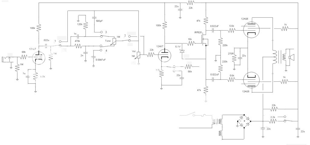
No tremolo so only need three triodes. But if you use a mosfet for the phase splitter then you can drop a triode. So one 12AX7 for the gain stages. The tone switching thing is the normal Tweed tone control but the other position of the three pole toggle switch is the Big Muff (or preceding that the Supro Thunderbolt) tone control.
While I know the mosfet PI should theoretically work as it is nothing but a source follower (with half the resistance above and below the mosfet) and they have been made using a IRF820 many times, still had to see it with my own eyes. Breadboarded a stripped down version of the schematic tonight, still needs to be wrung out but the PI seems to work. Will poke around on it latter.
Had some funky stuff go on with the inverter directly coupled to the 12AX7, went capacitor coupled and fixed bias on the mosfet instead.


Not pretty but it works. Need to build it now.
Not pretty but it works. Need to build it now.
Cool ideas.Not pretty but it works. Need to build it now.
Looking forward to the 'performance report'!🙂
I have come this far with mine until progress has stalled. I need to make a chassis and cabinet for it. I have been playing it with a speaker cabinet connected to the OPT with clip leads. I think there might be a little more gain left locked inside the preamp stages, and a little more "tone" hidden away inside somewhere, but it may not be worth squeezing it any harder.....time will tell. I have already sketched out a few more amps......one is a bit bigger and louder, the other is only 2 tubes, SE, and maybe 3 or 4 watts, and there is TV tubes 40 to 60 watts, which way next??????
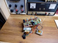
I have spent much of my time putting my workbench back together. The bench is nearly finished, made from mostly recycled materials. The work surface is about 20 mix and (mis) match hardwood flooring samples from a defunct carper shop.
The Knight power supply behind the board was dead. One of the 50 year old electrolytics had blown its end off, and the others were dried out, so I replaced every cap in the thing. I have owned it for 30 years and never had the case off.....It had 4 RCA black plate 6L6GC's in it. It now has 4 Chinese 6L6GC's in it!
The Fluke 407D still has all it's original parts, but works, so I'll leave it alone for now. My HP8903A had died again. I fixed it by playing musical circuit boards again.....I'm out of spare boards for this thing.
Attachments
Last edited:
And I thought, 'How long will that last?' And then I read,It had 4 RCA black plate 6L6GC's in it.
It now has 4 Chinese 6L6GC's in it!
I just wish that I took that thing apart when I got it rather than after 30 years of my abuse. That old power supply was one of the few that used 4 X 6L6GC to supply a rated 200 mA. Most were 2 tubes and 100 ma. In my usual style, I often sent the current meter needle way past the end of the scale at 300 mA. It never complained, and stayed in regulation up to almost 400 mA.
I'll have to stick those tubes into one of my amps and compare them to some NOS RCA's that I have.
I'll have to stick those tubes into one of my amps and compare them to some NOS RCA's that I have.
Had some funky stuff go on with the inverter directly coupled to the 12AX7, went capacitor coupled and fixed bias on the mosfet instead.
Not pretty but it works. Need to build it now.
Printer, I'm pretty sure that MOSFET concertina won't work as it is drawn. The problem is that when biased at B+/2 there's no way that the the outputs can swing when the signal goes positive (actually there's a few volts of non-linear play due to the Vgs). I'd recommend biasing at about 1/4 to 1/3 B+.
Had some funky stuff go on with the inverter directly coupled to the 12AX7, went capacitor coupled and fixed bias on the mosfet instead......when biased at B+/2 there's no way that the the outputs can swing when the signal goes positive....I'd recommend biasing at about 1/4 to 1/3 B+.
My version only has 165 volts of B+ to play with. I had to AC couple the mosfet and I settled on 1 meg and 2 meg resistors to set the bias at about 1/3 of B+. That resulted in the most output swing when the B+ sags below 150 volts due to screen current when pounding the output tubes with overdrive.....it sounds the best too.
I have made the direct coupled circuit work when I had 300 volts of B+ to play with and the driving triode's plate voltage is in the 100 volt range.
Printer, I'm pretty sure that MOSFET concertina won't work as it is drawn. The problem is that when biased at B+/2 there's no way that the the outputs can swing when the signal goes positive (actually there's a few volts of non-linear play due to the Vgs). I'd recommend biasing at about 1/4 to 1/3 B+.
It sort of worked, without the zener diode, probably not.
I did change it to about 1/4 B+, was going to post a new schematic when I had the amp done. Was planing on getting most of it done today but work got in the way. Should have it done some time this week.
Well it won't be called a work of art, a piece of work maybe. Forgot how long it can take to build a board, even a simple one like this. Eyeballed the board and guessed at where the parts should go. Probably can tell I started at the PS end and went left. Another half inch of real estate would have been handy. Tomorrow start putting parts in the chassis.
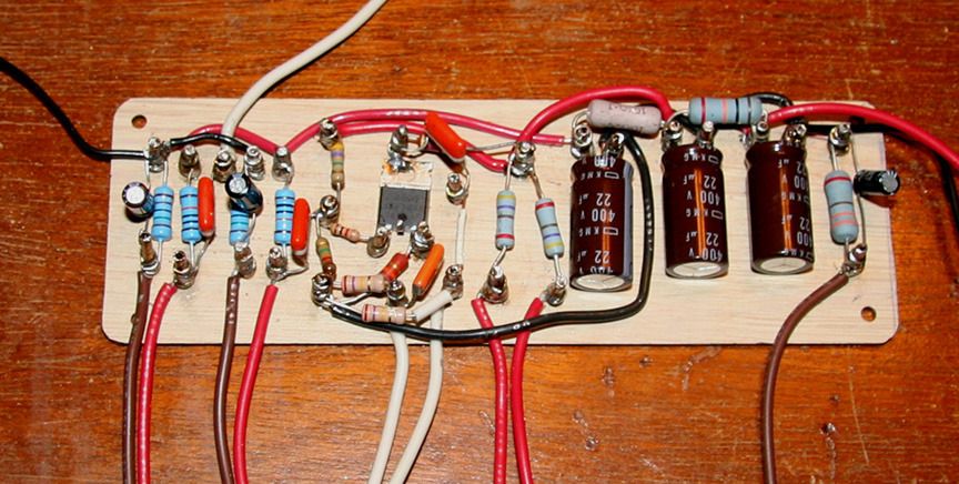
Have it up and running but I have some buzz from the first stage when cranked. Think some shielded cable will take care of it. Had some Sylvania output tubes which had different idle currents through them. Only around 10% but I felt it might be causing more distortion on the low notes than the amp should have. Changed them for some RCA that were about 1 mA away from each other. Seemed to have helped, or it just could be my imagination.
Running the output on 260V, increased the voltage but it did not seem to get me any more so left it where it is. Next time I'll add another inch to the board, is a little cramped. Think the limiting factor is the OT, mind you it was not designed to have dc going through it and it might be light on inductance. You get what you pay for I guess.
The Big Muff tone control seems, weird. Not sure if I like it, maybe I have it hooked up wrong? I'll go over it again later, spent too much time on it today. Otherwise it works as expected. Stays clean till it starts to break up and after that it gets more dirty and not louder. Need an efficient speaker if you want cleans. But then again that means that when you get dirty it will be loud.
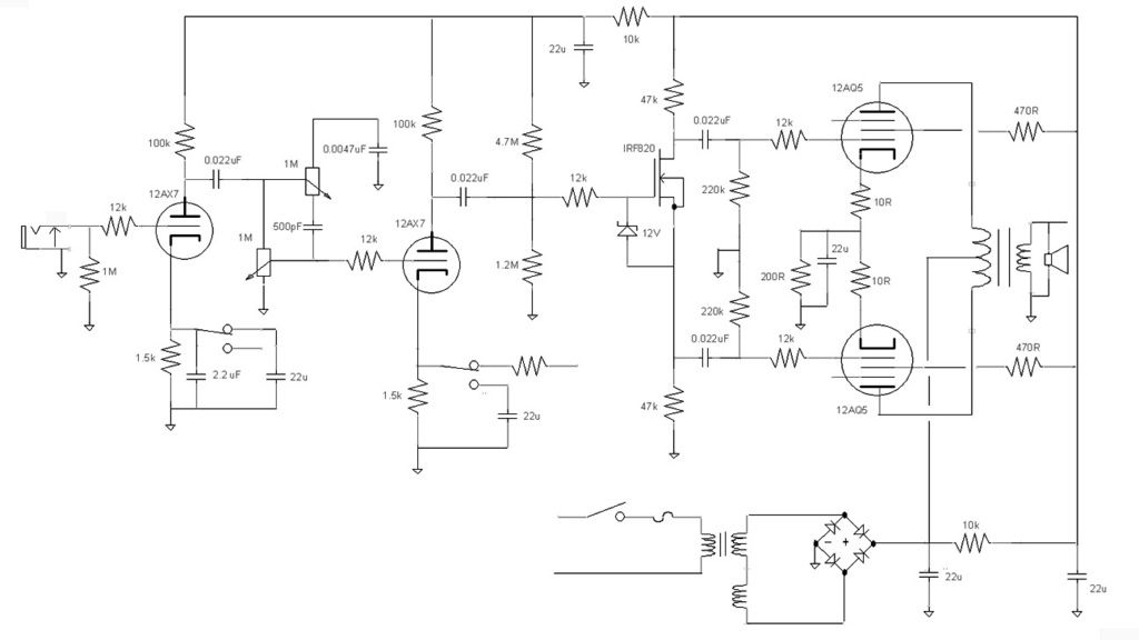
Finished schematic. Am going to remove the Big Muff tone control and add the NFB switch to give the amp a more cleaner mode. Otherwise the amp works well with the parts as updated. Again, the amp run on 250V, it sounds fine but the weak point I think is the output transformer. I am sure it would sound better with an OT that was really designed to be one. I did move some parts on the board. Moved the output cathode resistor and cap under the filter caps, put the rectifiers in its place.
I put 400V caps on the board, who knows, maybe one day I will change out the output transformer, flip the power transformer around and feed it to a doubler. Did that in another amp and puts out about 400V into a pair of 12AB5's, a 9-pin version of the 6V6. Maybe change the power supply resistors though.
Left out the switched NFB and cathode capacitor. Not a 100% physical layout but easy enough to make one from it.

Well my iron budget blew the $100 marker out of the water.....Everything else should be sub-$50 or so. Bought a distressed SS amp that had a 10" driver in it (that will eventually be replaced) that's serving as a great chassis and whatnot to put everything in. Once i get the edcor's in , I'll have the whole she-bang to get going. Switches and whatnot are already in the chassis.
Sometime tonight I'll Have to find a non-scribbled version of the schematic. I did just order the final bits that I didn't have laying around over lunch, so maybe by this weekend I'll have something substantial to show!
Sometime tonight I'll Have to find a non-scribbled version of the schematic. I did just order the final bits that I didn't have laying around over lunch, so maybe by this weekend I'll have something substantial to show!

well won't let me re-edit the above post....but when I sat down this morning I wasn't real happy with how the (above) layout was working.
Much better, As noted I'll be moving the turret board over some and things should even line up better:

Much better, As noted I'll be moving the turret board over some and things should even line up better:
- Home
- Live Sound
- Instruments and Amps
- The Hundred-Buck Amp Challenge