Re: Taking a break from the smell of soldering
Hi Butcher😀
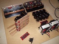
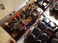
You could put the 100nf caps under the PCB, and please don't leave the big caps standing in the air.
Also, check if the big caps don't touch the copper bar, otherwise they will be constantly warm, not good.
Btw it looks like a serious amp.😉
chris ma said:work in progress
Hi Butcher😀
You could put the 100nf caps under the PCB, and please don't leave the big caps standing in the air.
Also, check if the big caps don't touch the copper bar, otherwise they will be constantly warm, not good.
Btw it looks like a serious amp.😉
Hi Carlosfm,
The 100uf big caps have above 1.5 times the thickness of that pcb clearance from the copper bar. I used a multimeter to make sure nothing is connected unexpectedly, can not trust the naked eyes no more 🙂
Standing up caps, oh yes, I tried but no matter which way I bend those legs the cap has to stand up anyway so I used the 0.1uf wima as support for it to sit on now. My original plan was to put the wima on the bottom of the pcb, but the smallest pair of pads for the 100uf cap is still too wide apart.
The Butcher😀
Oi Carlos, can I add the snubber directly in to the caps ?
(connected to + and - of the caps)
I'm restoring an old amplifier and I don't have space to add the snubber after the caps
(connected to + and - of the caps)
I'm restoring an old amplifier and I don't have space to add the snubber after the caps
XELB said:Oi Carlos, can I add the snubber directly in to the caps ?
(connected to + and - of the caps)
Of course.
chris ma said:
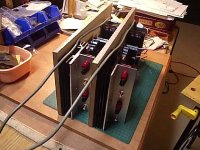
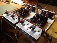
Right Channel. They replacing the Pan.FC 1500uf BrianGt GC , just sit on top of them for now.
The Butcher😀
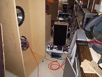
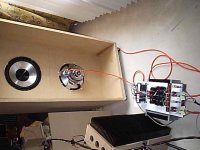
What model/brand are those subs? Nice work on the amp 😉
The drivers are:
MAX Performance, discontinued line, bought them cheap for $85cdn each..
Power==175W RMS
PEAK==350WATT
Imp==4 ohm
RDC==2.8 ohm
Fs==25Hz
Qes==0.62
Qms==2.9
Qts==0.51
Vas==248L(8.75cu.ft.)
Xmas==+/-6mm(0.24”)
Travel==1.1”
No%==0.627
BI=6.8TM
Mms==64G
Sd sq.M.==0.0531
MAGNET==56oz
SIZE==12”
Features
2" 2 layer voice-coil on aluminum bobbin
chrome ion deposited polypropylene cone with stress relief rings
Rubber surround
+++++++++++++++++++
The Butcher😀

homer09 said:carlos, to confirm:
the only difference is the beefed up capacitance?
Not only, look closer.😉
homer09 said:carlos, to confirm:
the only difference is the beefed up capacitance?
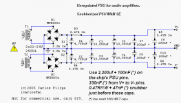
It seems like the snubber value as changed and now there is also a resistor after the 4,700uF capacitor....
My new PSU configuration is:
4x (4,700uF + 100nF) + 18,000uF + snubber
I did not test it.
I finished last night and today I went on vacation.... so I could not test it 🙄
I think this new MKIII snubberized PSU is easy to implement. 😎
Carlos, can you tell us how it sounds compared to the old version ?
XELB said:It seems like the snubber value as changed and now there is also a resistor after the 4,700uF capacitor....
Yes, it's a CRCCS PSU.

XELB said:Carlos, can you tell us how it sounds compared to the old version ?
Even more driving ability to the amp, and slightly more detailed overall.
Lower value resistors (0.47R instead of 1R) on the snubber work better.
CRCCS PSU
Can you translate de CRCCS part ? 😀


Even more driving ability to the amp, and slightly more detailed overall.
Lower value resistors (0.47R instead of 1R) on the snubber work better.
Great news 🙂
You just make me spend money... bad guy, bad guy.... 😛
With the speed that you make new things, I think I will have to buy an entire electronic shop! LOL 😀
On tuesday I will test it. Now I will enjoy the sun of the Algarve

- Status
- Not open for further replies.
- Home
- Amplifiers
- Chip Amps
- The (high-cap.) unregulated PSU for chipamps