Would there be any problem with this really crude inrush limiter setup? A resistor connected in series to each primary, a parallel bypass circuit with a switch on it you close after the amp is up.
1 x 10,000UF - vs - 10 x 1,000UF
Have any one ever tried using ten of 1,000 as the replacement of one 10,000 cap ( as it's said smaller cap is faster). If so, do we need to bycap each of them with 0.1UF or only one 0.1UF at the end?
Have any one ever tried using ten of 1,000 as the replacement of one 10,000 cap ( as it's said smaller cap is faster). If so, do we need to bycap each of them with 0.1UF or only one 0.1UF at the end?
Yes someone did indeed🙂 You only need the snupper at the end of that row of caps😉 That sounded pretty good to me, but I couldnt hear any difference as opposed to 10.000uF caps to any extended degree! Meaning: I could not hear the diff!!Have any one ever tried using ten of 1,000 as the replacement of one 10,000 cap ( as it's said smaller cap is faster). If so, do we need to bycap each of them with 0.1UF or only one 0.1UF at the end?
Steen🙂
A regulated PSU also needs a snubber
I am testing on my (test) LM338 regulated PSU.
After the LM338 I recommended a 47nf cap, as some of you know.
On the power amp chips I recommended 100uf caps in any PSU type (regulated or snubberized high cap. PSU), but I have recently found out that better results can be had with bigger caps (2,200uf), snubberized with 0,47R+47nf.
Keeping things the same on the amp, I am testing the regulated PSU.
A snubber right after the regulators makes IMPRESSIVELY AUDIBLE improvements.
Comparing to the unregulated snubberized high cap. PSU, the LM338 regulated PSU had a little less detail, "air".
Not anymore.😎
The snubber after the regs has to have very different values (if compared to unregulated).
In fact, I discovered a way to calculate the optimum value for the snubber, depending on the regulator used and it's specs.
Call me mad, but I think this is a revolution for regulated PSUs.
So much so that I'm still considering if I will make my findings public or not.🙄
In fact, I discovered a way to calculate the optimum value for the snubber, depending on the regulator used and it's specs.
This optimum snubber value is based in what you think will sound better or something else?
You're madCall me mad, but I think this is a revolution for regulated PSUs.
So much so that I'm still considering if I will make my findings public or not

 😉
😉 You can always register your work/investigation 😎
XELB said:This optimum snubber value is based in what you think will sound better or something else?
Like I said, it's calculated based on the regulator's specs.
The end result is a much better PSU, and much more important than that, a much better sounding one.
Carlos,
Is this based purely on you listening to it? or do you have any measurements to back up your new find 😉
Mike
Is this based purely on you listening to it? or do you have any measurements to back up your new find 😉
Mike
Like I said, it's calculated based on the regulator's specs.
The end result is a much better PSU, and much more important than that, a much better sounding one.
I didn't explain very well!
What I'm trying to say is:
Based on the regulator you use a "formula" to deduce the snubber value.
This formula is based in "math and scientific data” or was deduced by an experimental way, experimenting and listening for different regulator specs?
motherone said:Is this based purely on you listening to it? or do you have any measurements to back up your new find 😉
First was connecting again my test regulated PSU to the amp and listening.
---- dinner break ----
Second, there is an understanding of what a snubber does to a PSU.
Third, there was the obvious conclusion on what parameter would it improve when applied to the output of the regulators.
Fourth, there was a checking of the specs and graphs of that regulator, on the datasheet.
Fifth: the calculations for the snubber components.
Sixth: listening again.
XELB said:This formula is based in "math and scientific data” or was deduced by an experimental way, experimenting and listening for different regulator specs?
Not experimental, read above.
It was spot on, no change of components needed, it's playin' LOUD AND CLEAR, and I don't wanna stop listening to music tonight.😎
That's good newsIt was spot on, no change of components needed, it's playin' LOUD AND CLEAR, and I don't wanna stop listening to music tonight.

I am finishing my PSU.
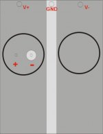
I will use an two layer PCB. Top layer for V+ and V- and bottom layer for GND.
I think this way the PCB will make a small capacitor between the top layer and the bottom one.
The picture is just an example for 1 cap in each V+ and V- side.
I will use 6x 6,800uF per rail. I hope this solution will lower the ESR 😉
After that I will test the snubber.
Can I test it in the output for the speaker ? (like it was for an Super Tweeter)
Attachments
steenoe said:Yes someone did indeed🙂 You only need the snupper at the end of that row of caps😉 That sounded pretty good to me, but I couldnt hear any difference as opposed to 10.000uF caps to any extended degree! Meaning: I could not hear the diff!!
Steen🙂
Thanks Steen.
BTW, Should I bi-cap each of them with 0.1UF/50V ? 😕
( fyi - I asked bcoz someone offer me 20 x 1,000UF (normal Elna, 50V) at cheaper price than 2x 10,000UF same brand. [10,000UF/50V ELNA is ~ US$ 3 each). 😉
BTW, have not seen many mentioned about ELNA cap (the normal blue ones. How is it compared with the Pana FC series)

XELB said:
I will use an two layer PCB. Top layer for V+ and V- and bottom layer for GND.
IMHO, I'd go for no PCB instead. Using a think hard-wired solid copper wire connect the Caps's pin directly might be better -- unless your PCB have very "thick (+width)" copper trace.
🙂
nina said:
IMHO, I'd go for no PCB instead. Using a think hard-wired solid copper wire connect the Caps's pin directly might be better -- unless your PCB have very "thick (+width)" copper trace.
🙂
I think the PCB is very width and I will choose the most thickness.
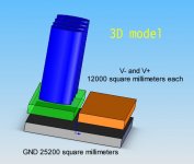
See the picture, I made a 3D Model with the two layers 😉
( V+ and V- on top and GND in the bottom)
I think this way the top layer will make a small capacitor with the bottom layer that could improve the PSU and the sound 🙂
I hope to be right. I will test it soon, than I will make a report. 😉
Attachments
XELB said:
I think this way the top layer will make a small capacitor with the bottom layer that could improve the PSU and the sound 🙂
I hope to be right.
why?

capacitor measurements
There are measurements useful in selecting and evaluating different capacitor combinations for filtering power supplies available here:
http://www.audioxpress.com/magsdirx/ax/addenda/505StamlerTables.pdf
There are measurements useful in selecting and evaluating different capacitor combinations for filtering power supplies available here:
http://www.audioxpress.com/magsdirx/ax/addenda/505StamlerTables.pdf
homer09 said:
why?
Like a battery, a capacitor has two terminals. Inside the capacitor, the terminals connect to two metal plates separated by a dielectric. The dielectric can be air, paper, plastic or anything else that does not conduct electricity and keeps the plates from touching each other.
Copy paste from ---> http://electronics.howstuffworks.com/capacitor1.htm
The idea is to use the PCB as a capacitor and circuit. 😎
From what I normally see here, you only use de PCB as a circuit.
XELB said:
Like a battery, a capacitor has two terminals. Inside the capacitor, the terminals connect to two metal plates separated by a dielectric. The dielectric can be air, paper, plastic or anything else that does not conduct electricity and keeps the plates from touching each other.
Copy paste from ---> http://electronics.howstuffworks.com/capacitor1.htm
The idea is to use the PCB as a capacitor and circuit. 😎
From what I normally see here, you only use de PCB as a circuit.
I understood how your PCB would act as a low capacitance capacitor, what i was asking is why do you think this will improve the sound or even have an effect on it?
For example,
When you use a Snubber the ringing is almost completely damped out except for the initial pulse.
When you use a small capacitor like 100nF the ringing doesn’t disappear but, the frequency is much lower.
(this is based in a PDF by Jim Hagerman and some carlosfm post’s)
I think this PCB design will act like a small capacitor and filter high frequencys.
I also want to try this PSU with the snubber and see( ear ) the results.
XELB said:I think this PCB design will act like a small capacitor and filter high frequencys.
I also want to try this PSU with the snubber and see( ear ) the results.
You will find out that the snubber is much more effective.
You can bypass as you want, parallel caps as you want, the result will not vary much.
Some have the oppinion that lower bandwidth, slower amplifiers (discrete or integrated) sound better.
I don't.
The secret in on the PSU implementation.
I would compare an LM3875/3886/4780 chip as the equivalent to some Burr-Brown op-amps, like the OPA627/37 and some others.
Try them and hate them, or make it right and love them.😎
I am enjoying (listening) to an impressive preformance by any standard with a chip amp that I would not think possible some years ago.
Come to think of it, the chip is still the same: the LM3886.😎
That's why I always insisted that, although a chip amp, the chip alone doesn't make the amp.
Disgrace or high-end, both can be done.
- Status
- Not open for further replies.
- Home
- Amplifiers
- Chip Amps
- The (high-cap.) unregulated PSU for chipamps