Something like that would probably go to a board shop. When you want the sharpie method is for something as simple as the power supply and bias boards in the tube amp - and you get them that afternoon. If I do a complicated one-off its perf board to the rescue. Used to use the sharpie method for everything - back when the cheapest 14x14 you could get made would be $300 a board - in quantity. The 2-sides one in the sand amp was several months in layout before I was satisfied enough to dunk it. At todays prices it would be stupid to make by hand, but not back then.I am sorry, but no way. I always start with a 2-sided PCBs even for prototypes, can't imagine drawing this by hand. I know what I speak about, 40 years ago I made my proto boards by hand. Depends what we want to do and what we expect to get. Too many variables 😉.
View attachment 1053781 View attachment 1053782
I’ll probably go with KiCad myself - I’m still running some old package from 20 years ago which still works. But will die with the computer when it does. The XP is still running great - but the hardware is developing minor problems. Only a matter of time before they become major ones. I will be looking for a good used Win7 desktop to replace it. With an Intel processor (required to run ANY DJ console - they all act stupid on AMDs).
Attachments
I found it a nightmare getting some semiconductors.You can't make a semiconductor working from home. The pandemic really upset the supply chain of solid state semiconductors and now a war to affect the supply of tubes. It will probably be 2025 when and if things get back to normal.
One of my worst fears about my career choice has come to fruition. Technology is like the tower of Babel story. It builds on itself. Pull out one of the foundation pieces and it all comes down, hopefully, temporarily.
Some of the PIC micro's I use are pin compatible with others if I change the code a bit.
I use ad9201 A2D's and they soared to £15 on RS Components.
Seemed to be similar prices elsewhere.
So had a look at Ali Express and they are about £1 each.
Had trouble sourcing an lcd display which was £6 on RS.
Found a seller on ebay and he sold me 24 for 30p each !
A couple didnt work but at 30p its not a problem.
I use 4700uf caps and on RS they were £2.20.
Got 10 on ebay for £0.60 each.
Rs sell usb sockets for £1.30
Got some on CPC for 25p each.
It definitely pays to shop around.
While Chinese stuff isnt always good I havent had a single return.

I fully agree and use Eagle for most everything I currently make. Super simple things can still be drawn with a Sharpie if you need something fast and ugly. When I said simple, I meant 4 diodes and 4 big electrolytics kind of simple.I am sorry, but no way. I always start with a 2-sided PCBs even for prototypes, can't imagine drawing this by hand. I know what I speak about, 40 years ago I made my proto boards by hand. Depends what we want to do and what we expect to get. Too many variables 😉.
View attachment 1053781 View attachment 1053782
EasyEDA: Simple version should do: https://easyeda.com/editor
EasyEDA seems to be a web based product. I don't want to go there, as I have been burned in the past when web based apps disappear.
That's my current thinking. KiCad has recently released V6.something, so I'll get it and try it for a small test board that may or may not ever get made. I have used Eagle for nearly 30 years, and Mentor Graphics at Motorola for 20+ years. We had just switched to Cadence PCB tools at Moto about 2 years before I retired. This will mean learning a 4th PCB design tool.My suggestion is to go Kicad, you'll have a large community to draw from and it has an incredibly large library of parts.
You may find interesting that complete Eagle project can be imported into KiCad. It will add all unknown parts to autogenerated custom library.KiCad has recently released V6.something, so I'll get it and try it for a small test board that may or may not ever get made.
It is, but AFAIK there's a local version you can download along with the auto-routing server... I doubt it would disappear though since they just added the pro version, and it funnels business to LCSC and JLCPCB.EasyEDA seems to be a web based product. I don't want to go there, as I have been burned in the past when web based apps disappear.
I also don't make schematics in EasyEDA. I just use it to layout PCBs. I do schematics in Scheme-it.
In the meantime, I'll check out Kicad... I've avoided it in the past because I thought it was part of KDE because almost everything that starts with a "K" is KDE related on Linux...
Last edited:
Interesting device, for experimentation maybe:
https://www.st.com/en/automotive-infotainment-and-telematics/tda7901.html
https://www.st.com/en/automotive-infotainment-and-telematics/tda7901.html
Did you find out where is the fun now?I'm interested in knowing where it is based now.
I made my own Bluetooth speaker a few years ago. Making the wooden box was the hardest part. The guts involved a Chinese class D board that had two TPA3116 chips, one mono strapped for the sub, and the other stereo for each channel. The 20 volt battery board, Lithium cells, Bluetooth receiver, and speaker drivers all came from Parts Express. I used separate components so that I could add input jacks for playing my guitar or synthesizers through this thing. It was a bit bigger than the one shown in the above video, probably a bit louder too.
My BF wanted a "bluetooth speaker"... I considered crafting one for him by hand, but it was more sensical to buy this: https://www.amazon.ca/Bluetooth-W-KING-Speakers-Wireless-Waterproof/dp/B08L4VGN34/ref=sr_1_6?crid=2IANNZG7DTKIH&keywords=w-king&qid=1652458571&sprefix=w-king,aps,62&sr=8-6
It's as loud as a descent "Ghetto blaster" that ran on 10 D cells... If it's actually 60W, I'll eat my tubes.

It's as loud as a descent "Ghetto blaster" that ran on 10 D cells... If it's actually 60W, I'll eat my tubes.
I began to make my own PCBs in a time and place with no Sharpies.Super simple things can still be drawn with a Sharpie if you need something fast and ugly. When I said simple, I meant 4 diodes and 4 big electrolytics kind of simple.
So I would design my PCB by hand, with a pencil, on 0.1" grid graph paper. Once the design was complete, I would tape the paper down on the copper clad board and use a nail (didn't have an awl) to make a tiny dimple in the copper at every hole location. Then remove the paper, and connect the dots with resist, by hand, using the dimples in the bare copper board, and the drawing on graph paper, to reproduce the track pattern.
And the resist? Ordinary household oil-based paint. The special resist-pen consisted of an ordinary ball point pen that had run out of ink and was ready to throw away - I would pull out the metal tip, poke one of my mother's sewing needles in from the ink side, and pop out the tiny little ball at the tip. With the ball removed, you had a very fine nozzle. Now suck some oil paint up into the refill, and there is your free, custom, hand-made PCB resist pen!
As with most things, the more you use a technique, the better you get at it. In my early twenties I laid out and built an entire stereo Dolby B board using this method for example, and an entire audio function generator based around a quad op-amp that I ended up selling to my college physics lab. I used the same technique to build multiple fairly complicated audio power amplifiers, including some later ones based on integrated circuits. Circa 1988 or 1989, I remember designing and building an audio amp for a classmate using a pair of TBA810 chips, configured in bridge mode so he could get more power.
Necessity is the mother of invention...when you don't have fancy tools or the money to get them, you find ways to work with what you can get your hands on.
And there are always benefits to such approaches. I think designing so many PCBs entirely by eye left me with a much better ability to connect a schematic drawing with a physical layout, and vice versa. Standing parts like resistors on end let me shrink my PCBs to very small sizes compared to today's computer layout software - a vital feature, since I had no money, and bare copper-clad board wasn't cheap. I had to make every square inch count.
I'm too lazy to make PCBs any longer, and often solder components directly onto protoboard. I virtually never plan a layout in advance, simply place parts and solder, one part and one connection at a time, until the circuit is complete. Apparently my brain can still connect schematic and physical layout pretty well, because the stuff always works after I finish it, usually with very little debugging and few or no mistakes found.
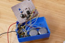
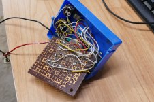
As a "for instance", not long ago I built a guitar (speaker) cab emulation filter using multiple op-amps and a JFET or two. I designed the circuit using LTSpice, and built it straight onto proto-board. It's a fairly complex set of adjustable filters that roughly reproduce the intentionally far-from-flat frequency response of a typical guitar loudspeaker. I crammed the whole thing onto a tiny protoboard probably no more than 2"x3", with space left over.
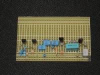
I couldn't find that little protoboard today, but here are a couple of images of another circuit I designed, simulated, and built straight onto proto-board a few years ago. Four active devices and a fairly complex filter producing an EQ curve for a custom guitar amp - and it all fits on one-half of a 2"x3" proto board!
-Gnobuddy
Attachments

You guys are amazing to me. I've never made my own board from scratch as you describe, but my best friend Matt made a 300W "Brute amp" like that...
Not photo board though. He needed ferric acid etc.
I'm so thankful for modern EDA and fab 🙂 Like George said, a Sharpie etc is good for a simple rectifier board.
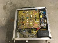
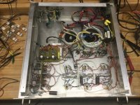
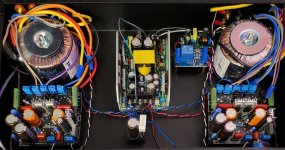
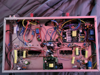
As an aside, here's the (effectively) the same amp point to point vs PCB. The point to point amp is "integrated", the PCB is a straight power amplifier.
The point to point uses a linear supply for B+, the PCB doesn't.
Not photo board though. He needed ferric acid etc.
I'm so thankful for modern EDA and fab 🙂 Like George said, a Sharpie etc is good for a simple rectifier board.
As an aside, here's the (effectively) the same amp point to point vs PCB. The point to point amp is "integrated", the PCB is a straight power amplifier.
The point to point uses a linear supply for B+, the PCB doesn't.
Attachments
Here we have seen examples of "real DIY" the kind where you find a way to make what you want with what you have. DIY PC boards, I have even made a crude PC board with A Dremel like engraving tool a long time ago. While digging through a box of old junk I found a germanium fuzz box I made in the 1960's. The design was "custom engineered" by taking a friend's VOX Tone Bender apart and tracing its schematic. A crude implementation, but it worked, and still does.
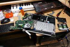
While looking up the photo of the fuzz box, I discovered a DIY repair of a different kind. In 2014 I bought an ASUS Core i7 laptop from Newegg. Within a few months it developed a weird issue, but I worked around it. After about a year it became unusable as it would insert random key presses whenever the slightest vibration occurred. The big label on the box proclaimed a "two year rapid replacement warranty" so I called ASUS for an RMA. They told me that I only had a 1 year warranty and I could send it in for evaluation which would cost $50 just to determine the cost of repair. I explained that the ASUS box stated that I had a 2 year warranty. They explained that the W12 on the bottom of the PC showed that it only had a 1 year warranty. Multiple discussions with ASUS and Newegg got nowhere so I gave up. I have not bought an ASUS product since and I avoid Newegg whenever possible.
I ripped the laptop apart and found that the laser cut bracket that held the hard drive had a sharp edge that had cut into the flex circuit that connected the keyboard to the motherboard. Attempts to repair the flex killed it. A search on Amazon found a replacement keyboard in China for $15. About a month later I had a new keyboard, so the ASUS came apart. The keyboard is the first thing that went into the case when the laptop was built so it's the last thing to come out. It's held in by ultrasonic staking of plastic pins on the outer housing, so it's removed with wire cutters and reinstalled with a hot soldering and a junk tip. an SSD replaced the spinning disk while it was apart. The amazing part is that it's still working today with no issues.
Attachments
Home, Products, Desktop ClientAFAIK there's a local version you can download a
Choice: Windows(At least Win7), Linux(At least 4.9), Mac(At least 10.12)
Supposed to be a link to a Tutorial PDF; not a good sign that this gives an error. There IS a working quickstart:
https://docs.easyeda.com/en/FAQ/Client/index.html
Shows "Full Offline" mode for the very concerned.
I use KiCad version 4.0.5+dfsg1-4~bpo8+1, release build.Which version?
I sometimes have to use Eagle at work, but dislike it because it is very easy to make a schematic that doesn't netlist properly. I sometimes abuse Eagle as a block diagram drawing tool.
When I was still single, I used to etch my own printed circuit boards in the kitchen of my apartment, using a plastic aquarium with etchant. I once managed to make a usable PCB for a circuit with a 100 pin, 0.5 mm pitch TQFP integrated circuit. I drew the layout with a 0.5 mm fineliner on paper with a light blue 1 mm grid, copied it at 50 % of the original size to a transparency, used a fluorescent lamp to copy it to the photoresist layer on the PCB material, developed and etched it. I had to do it three times to get one usable PCB. It was a double-sided PCB with a ground plane on the other side.
When I moved in with my partner, I took my aquarium with etchant with me, but never dared to use it anymore. I didn't want to damage her kitchen with drops of etchant and I definitely didn't want the cats to come in contact with it. Besides, unless there was a very good reason to use a PCB, I preferred building circuits on perfboard anyway. After a couple of years, I brought it to a site where they collect chemical waste.
I still like perfboard more than PCBs, but when there is a good reason to use a PCB, I now use KiCad and Eurocircuits.
Well, that sort of spec point is fairly normal for automotive stuff. But an experimenter might want to see what power it hit before the curve kicks up.They brag about 117db SNR but spec power at 10% THD LMAO
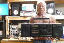
I still have my 1990's vintage "blaster" it needs 10 D cells AND 4 double A's. In the 2010's I built a pair of high efficiency horn speakers. In order to break them in I connected them to the Panasonic and set the dial on the local rap music station or the Latin disco station with the volume cranked to the edge of distortion every morning before leaving for work for over a week. It was surprisingly loud. My neighbor loved it......NOT. His kid played in a death metal band all through high school. I was just evening the scales a bit. That boom box served duty as a keyboard amp fed by a Roland JV1000 through the mid 90's and into the 2000's. I still have the Roland too, but neither have seen power in at least 10 years.My BF wanted a "bluetooth speaker"... I considered crafting one for him by hand, but it was more sensical to buy this: https://www.amazon.ca/Bluetooth-W-KING-Speakers-Wireless-Waterproof/dp/B08L4VGN34/ref=sr_1_6?crid=2IANNZG7DTKIH&keywords=w-king&qid=1652458571&sprefix=w-king,aps,62&sr=8-6
It's as loud as a descent "Ghetto blaster" that ran on 10 D cells... If it's actually 60W, I'll eat my tubes.
Attachments
Member
Joined 2009
Paid Member
- Home
- Member Areas
- The Lounge
- The fun has gone out of DIY audio ?