Thanks, Patrick
that confirms what I thought- a voltage regulator has to (more or less) keep up with the amp that he is supplying.
And the LM338 is not really a modern part...
I have already made a capacitance multiplier board that works fine (Darington made of separate BJTs).
I will give it a try for the M2.
And LM317/337 for the F5P
Boris
What transistors are you using for the Darlington ?
We used 2SC5200/2SA1943, with KCc3503/KSA1381 drivers.
But I guess TTA004/TTB004 might also work.
Fran used 317/337/338 in his F5Pi US without problems.
Patrick
We used 2SC5200/2SA1943, with KCc3503/KSA1381 drivers.
But I guess TTA004/TTB004 might also work.
Fran used 317/337/338 in his F5Pi US without problems.
Patrick
Hi Boris,
I used a dual lm317 supply (PCB with a talema transformer and dual lm317 configured as +/- ) for the front end and the Xen CregC++ boards using 2x lm338 for output stages.
4 supplies in total, 2 for front end left and right, 2 for output stage left and right. I used a single custom transformer with 4x secondaries for the output stage.
Fran
Thanks, Fran.
I guess with dual LM317 you mean an LM317/LM337 pair?
Is there a link for the Xen CregC++ schematic/board?
I guess with dual LM317 you mean an LM317/LM337 pair?
Is there a link for the Xen CregC++ schematic/board?
They are just as old as the 338, not ?I used BD139/TIP3055 and BD140/TIP2955.
It is the design from Elliott Sound AU
🤓
Patrick

I guess with dual LM317 you mean an LM317/LM337 pair?
No, we have a small board using with 2x 317, so the we can configure them as +/- supply as well as otherwise.
The reason for 2x 317 is that we can use 317HV for higher voltages.
There is no HV equivalent for the 337.
Patrick
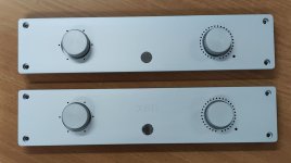
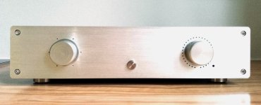
Someone asked about the frontend as a preamp.
As already mentioned in post #29 :
https://www.diyaudio.com/community/...tage-perfectly-integrated.406024/post-7524606
We have a working prototype.
But we shall only publish when it is fully integrated, in a proper case, with volume control, power supplies, etc.
Then measure final performance in that state, not just the amplifier module.
The case will be shipped next week.
So please be patient.
The input JFETs will be Toshiba 2SK246BL/2SJ103BL.
The output stage Fairchild FQP3N30/3P20.
As usual, whatever you can't get, we'll supply.
But of course they are many other sources around.
Thank you for your interest,
Patrick
Attachments
Someone asked about matching of the optocouplers in the M2OPS.
The Current Transfer Ratio (CTR) of the optocoupler is part of the closed loop bias control.
Its value is one of the factors in determining the bias control open lop gain.
If you want identical channels, it is better to match them, as the tolerances within each grade is rather large.
To measure CTR, you only need to rig up a very simple setup :
https://en.everlight.com/wp-content...-CTR-Measurement-and-Calculation-Ver1.0EN.pdf
They are not expensive. I would just buy 10 pcs and pick two with the closest match.
If you happen to have more matched pairs, you can either keep them as spares, or share with other builders.
Patrick
Elliott has one (near the bottom of the page), with all details how to build.
https://sound-au.com/articles/squarewave.htm
And 9V battery supply is more than plenty.
We made one, and it works.
Patrick
.
Attachments
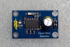
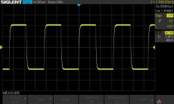
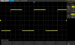
You can tune both frequency and sharpness of the square wave by changing some resistor values.
With 9V battery, you can get ~8V pk-pk output.
Of course you will need an output decoupling cap (MKP) and an attenuator before connecting to the F5Pi.
Patrick
.
With 9V battery, you can get ~8V pk-pk output.
Of course you will need an output decoupling cap (MKP) and an attenuator before connecting to the F5Pi.
Patrick
.
Attachments
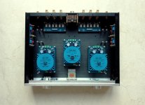
Someone asked about the frontend as a preamp.
https://www.diyaudio.com/community/...tage-perfectly-integrated.406024/post-7712173
A preview.
Shall open a new thread when fully functional.
Will take a couple more months.
Patrick
.
Attachments
- Home
- Amplifiers
- Pass Labs
- The F5Pi -- F5P Voltage Gain Stage + M2 Output Stage = Perfectly Integrated