What does the edge look like, either saw or knife. It might not work with [Bradford PolyMax] polyester fibres, They need to be cut rather than sawn. If only somebody near here had stock, I would go and take a look.
It’s a snap off utility knife blade, you should be able to get them from lots of different places. Like a long Stanley knife when it’s extended.
Best thing for poly-insulation is a well sharpened sickle ! Saw a slot in a length of ply and then lay it flat and support either side. (couple of sawhorse)
Lay the poly down and use the sickle vertically in an up and down motion through the slot. Like old style pit-sawing 🙂 Lay and/or clamp a board either side above if needed.
The curvature of the sickle ensures a clean fast no tear cut from top and below. Just be aware of the blade below !! it is more advanced below you than you expect...watch your jewels!!
I have shown this to our local building inspector who then promoted it to tradies and now used sickles are becoming harder to find.
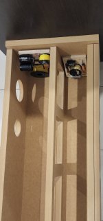
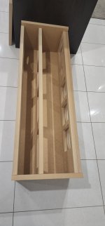
Hi, I got my panels over the weekend and just did a dry fit of the cabinet to get a feel. I placed the crossovers inside and being how chunky they are, thinking where to place them (needs to be placed inside as I've already cut holes for speaker terminal).
1. I could place one of them near the rear port as in the picture but not sure if it would affect the air movement near the port?
2. What if I mount them to the bracing inside. Could it restrict air flow?
1. I could place one of them near the rear port as in the picture but not sure if it would affect the air movement near the port?
2. What if I mount them to the bracing inside. Could it restrict air flow?
Attachments

That's what I had planned too but it won't be easy if you had to access it later on? I'm thinking if it would be a bad idea to mount both XOs to the main brace...?I had them mounted at the bottom and at the back panel (closer to the drivers they had to go to)
Also things like reduced box volume due to big XOs, are such things negligible? Not sure if Joe has accounted for such things when box size was determined?
Anything that restricts the flow near the ends of the ports, they can cause vortexes (air eddies) to form. These resists the action of the port (an acoustic resistance). Some years ago we played around to different puffy materials of different types near and in the port. It was surprising to see how little it took to make the port become 'aperiodic' and that it ceased to act as a reflex, in the manner of a Helmholtz Resonator. Basically, the double peak and saddle of the impedance as LF tuning, this is showing that the Helmholtz Resonator is working properly. That can easily be flipped and now you see just a single peak. It made it look like a sealed box when you didn't want a sealed box. You had turned the port into a resistive vent.
Allen, I am sure you are a bit of an expert on this, maybe put in your tuppence worth?
Allen, I am sure you are a bit of an expert on this, maybe put in your tuppence worth?
Thanks Joe. I'm not an expert but I have some suggestions.
Impedance measurements will give useful data. Once you're set up for them you can run all the tests at once and then be done with it. Try it with an obstruction at various distances.
Look for changes of frequency indicating a change in the mass of air in the port, then try compensating the length. A change in level would indicate resistive losses. Cross check the effect with relative pressure measurements.
It's important when theorising not to expect the same behaviours when comparing scenarios of continuous air flow with acoustic waves. That said, any changes in direction or shape could potentially have some degree of secondary effect. (Edit: and may also affect the maximum output you can get from the port.)
It's otherwise interesting to consider automotive port construction, purely from a geometric point of view, and only as a starting observation.. since it bears a resemblance to this question. Here I've shown the distance from the port where the obstruction leaves enough gap around the edges to equal the area of the port proper...
Last edited:
Thanks Allen, that is where it definitely shows up!Impedance measurements will give useful data
If it's not a good idea to mount it near the port, would it be better to mount at the main brace?
I am concerned about the inductors maybe becoming to close to the magnetic structures of the driver(s). Also, whilst likely to be of less of an issue compared to the port, the Main Brace is always a comprise between the act of bracing and not affecting the box acting as a single volume. In most commercial speakers, the rear panel is often, for the reasons discussed, is the most favourable place for the crossover. In the Elsinores, there is a limited space on the bottom in front of Main Brace and space around 220mm x 170mm - it is tight and has to be mounted through the bottom driver aperture of 145mm diameter. I know this is tricky and my Black PCB can do it just, but not easy. But there it is well below the port and does not affect the Main Brace.
So this is what I use as damping:

The problem is that you get 8 Sheets and you only need one sheet IF you get the 580mm wide sheet. You can also get it in packets at 430mm wide.
Here is how a 580mm wide sheet gets cut:

The 160mm part needs to be split into 4 layers, so in total you get ten cut pieces, one per box.
This does for one pair of Elsinore boxes from one sheet, so the problem is that you get seven sheets left. If you get the 430mm wide sheets, then you will clearly need two sheets and have more left over.
Maybe you can let it be known around the place, just how good stuff is if you are into DIY speakers and maybe somebody might put their hands up.
I am about to buy a packet of eight within a week or so, I am in Sydney so I can accommodate, come around and pick it up.
Cheers, Joe
.

The problem is that you get 8 Sheets and you only need one sheet IF you get the 580mm wide sheet. You can also get it in packets at 430mm wide.
Here is how a 580mm wide sheet gets cut:
The 160mm part needs to be split into 4 layers, so in total you get ten cut pieces, one per box.
This does for one pair of Elsinore boxes from one sheet, so the problem is that you get seven sheets left. If you get the 430mm wide sheets, then you will clearly need two sheets and have more left over.
Maybe you can let it be known around the place, just how good stuff is if you are into DIY speakers and maybe somebody might put their hands up.
I am about to buy a packet of eight within a week or so, I am in Sydney so I can accommodate, come around and pick it up.
Cheers, Joe
.
Hi Joe, so the thickness of this R3.5 Polymax is 180mm. For the 160x1160mm piece, it's cut into 4 layers and that means each layer is 45mm. This is much thicker than what's specified in the website which says 25mm?
Also for the other pieces you mentioned use the full thickness (which is 180mm) from the Bradford Polymax which is again much thicker than the website specified 75mm thickness. Can you please confirm this?
Also for the other pieces you mentioned use the full thickness (which is 180mm) from the Bradford Polymax which is again much thicker than the website specified 75mm thickness. Can you please confirm this?
As you can imagine, any design over time can be changed or improved. Yes, the overall increase in fill going from R3 to R3.5 does in crease the lined area and hence the total, even with R3 it was actually more than 25mm and I have said before, just slice into four, that is the main thing. And Actually, to boot, it makes the job easier.
When you are finished, you will end up something closer to 40mm, which is about right. Just use scissors to even them out, there will be stuff on the side as losses when you have finished cleaning them up. Just take your time and you will end up with something that looks a bit like a mat.
But you are right, I will change the reference to 25mm and give more information on the website.
You mean to 40/45mm and 75mm changed to 180mm rightI will change the reference to 25mm and give more information on the website
- Home
- Loudspeakers
- Multi-Way
- The "Elsinore Project" Thread