So it is a question whether to bi-wire or not?
You can bi-wire, but not a good idea to bi-amp. The current EQ, where the aim is to draw the same power at all frequencies and attain a near zero current phase angle of the amplifier, that does not work when bi-amping, but should still work when bi-wiring. The Xover 'split' does need to be done intelligently. 😀
Do you think there is a significant effect from bi-wiring these speakers? I had wired up the crossovers using a single set of binding posts on my xover box.
Thanks!!
Do you think there is a significant effect from bi-wiring these speakers? I had wired up the crossovers using a single set of binding posts on my xover box.
Thanks!!
Same here. By the way this Xover works, there may well be no advantage to bi-wire and bi-amping is a definite no.
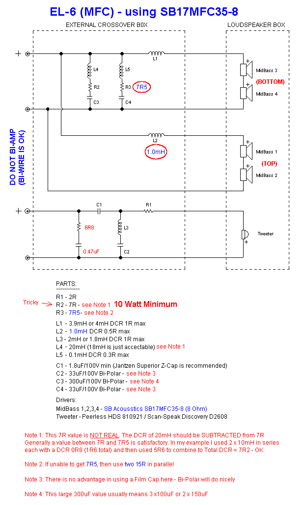
But if anybody wishes to bi-wire, then how is shown below (MFC example):
Hi,
I don't have the floor space for those nice speaker so I'm wondering if I can use them on top of a hifi furniture that is 700mm from the floor. Thinking of putting the speaker upside down to get the mid/tweeter closer to ear height. Flipping the front and the main brace would do the trick?
Or this is a bad idea?
/johan
Never thought about that. But it may well work by getting the tweeter near ear height. You could always revert to more normal operation later. So it is up to you, but the answer is yes, it should work, but of course the room will be a factor too, but that is always a factor anyway.
.
Last edited:
The Xover 'split' does need to be done intelligently. 😀
Joe (or ANYONE for that matter!)
Xover Split being done intelligently, not sure if this is a dig

lol...
My last post had zero responses.. Tough crowd....
I guess had too many questions, so will keep this shorter...
I did not separate the tweeter wiring in the cross over as much as Joe's diagram suggests.
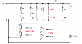
The attached shows more or less how I wired my xover figuring I would not bi wire. Would there be an improvement in my speakers if I re-wired ...was this done "unintelligently" ? (tong in cheek guys!)
Attachments
I took that to mean that this implementation has so far been based on theory. Yes, your crossover will work properly as you've shown it.Xover Split being done intelligently, not sure if this is a dig
By the way, bi-amping should be a straightforward proposition, with a few moments of crossover simulation. Maybe we should have a master class on impedance compensation...
Yes, your crossover will work properly as you've shown it.
Correct.
Maybe we should have a master class on impedance compensation...
Except that it is not 'impedance' compensation. This is about current EQ and where the flat impedance seems to be the aim, but it is simply a byproduct.
For example, if you use current EQ - making the amplifier produce the same current at all frequencies being the real aim, then you have effectively cancelled out the output impedance. So now that looks like the aim, right? Well, yes and no. What is the actual goal is controlling the current going through the voice coil, so no matter what amplifier you use, the current is actually controlled regardless. So the VC current is always optimised no matter what kind of amplifier you use.
It is based on very basic premises and also short-cuts the "current-drive" versus "voltage drive" arguments.
Edited the rest out....
.
Last edited:
I Yes, your crossover will work properly as you've shown it.
Maybe we should have a master class on impedance compensation...
Thank you, now I can stop beating myself up for not following directions exactly!!! And may be time to re-consider capacitor choices !
I would love to see a thread on impedance compensation...
I would love to see a thread on impedance compensation...
Based on past experience, that isn't going to happen.
Sigh.
Correct.
This is about current EQ...
.
Joe, you hit submit half a second after my last response, and ty for also chiming in. Regardless of the detractors, I believe I understand what your aiming at. le Im new to audio DIY, but I don't under stand how (or why) anyone thinks potential matters. It in it self does not create a magnetic field, which is the force responsible for what we hear. I may not be a smart man, but I know how sound is made lolol... I do see the importance of voltage though, (intuitively, with zero science to prove it) I believe a collapsing magnetic field across a coil absolutely needs voltage to overcome induced currents, and since that field is always changing, I cant help but wonder if two opposing coils properly managed is a better design. I digress...
I am curious though, I would guess the woofers need more current than the tweeter, more mass to move, but than the higher frequency of the tweeters may negate this intuition.. How does someone like yourself reconcile what ideal current eq is ? Is it based on db per watt across the frequency response of that driver ? I know these are probably silly questions, may be not ideal for "elsinore" thread, but I honestly wish to understand more.
but I honestly wish to understand more.
We all do. 🙂
Not saying that voltage is not important. I need to write this down with full descriptions, maths, measurements that include distortion and so on, and then make the case. What I will be doing is measuring the distortions of both the voltage and current of the amplifier. Ideally they should both the same, but they are not. There are definitely some things we know, but they seem to be ignored by so many. Then there are folklores that the physics just don't support, like the idea that the amplifier can contribute to the electrical damping of a system. That is just not the case. The most misleading explanation is the shorting with a wire the terminals of a driver and that the cone now becomes harder to move. That one is everywhere and can be debunked by using Thiele-Small Parameters, just one single equation they supplied: Electrical damping (Qe) = (2PiFsMmsRe)/(BLi^2). If Re is infinite, there is zero electrical damping damping and Re can only exist as a loop and must include the amplifier's output impedance. An open circuit Re proves nothing, it destroys Qe to infinity. The equation makes it clear that only "L" wire in the magnetic gap, the only only electrical damping occurs there. Re makes damping worse, the amplifier's output impedance can only make the electrical damping worse because it can only make Re a larger value. There is no mysterious damping by the amplifier at all.
I have to be patient. I will produce a full case study and at the centre is that all amplifiers, of any kind, are simply different current delivery systems, in time you will have an opportunity to read. It is impossible to set it all out in a few posts. An extensive case needs to be set out that others can examine in full.
A rose by any other name would smell as sweet.Except that it is not 'impedance' compensation. This is about current EQ and where the flat impedance seems to be the aim, but it is simply a byproduct.
Huge support for your work!
Here here Joe!
I totally agree with your explanation and theories and I cant wait to read your report.
Your points chime perfectly with my theory on fundamental design errors in loudspeaker drivers... I believe the lack of attention to addressing stored energy (ringing) in loudspeaker transducers is directly linked to the myth of back EMF/electromagnetic dampening applied by the amplifier which you so astutely identify above.
We all do. 🙂
Then there are folklores that the physics just don't support, like the idea that the amplifier can contribute to the electrical damping of a system. That is just not the case. The most misleading explanation is the shorting with a wire the terminals of a driver and that the cone now becomes harder to move. That one is everywhere and can be debunked by using Thiele-Small Parameters, just one single equation they supplied: Electrical damping (Qe) = (2PiFsMmsRe)/(BLi^2). If Re is infinite, there is zero electrical damping damping and Re can only exist as a loop and must include the amplifier's output impedance. An open circuit Re proves nothing, it destroys Qe to infinity. The equation makes it clear that only "L" wire in the magnetic gap, the only only electrical damping occurs there. Re makes damping worse, the amplifier's output impedance can only make the electrical damping worse because it can only make Re a larger value. There is no mysterious damping by the amplifier at all.
Here here Joe!
I totally agree with your explanation and theories and I cant wait to read your report.
Your points chime perfectly with my theory on fundamental design errors in loudspeaker drivers... I believe the lack of attention to addressing stored energy (ringing) in loudspeaker transducers is directly linked to the myth of back EMF/electromagnetic dampening applied by the amplifier which you so astutely identify above.
Here here Joe!
I totally agree with your explanation and theories and I cant wait to read your report.
Please keep in touch.
Here here Joe!
Your points chime perfectly with my theory on fundamental design errors in loudspeaker drivers... I believe the lack of attention to addressing stored energy (ringing) in loudspeaker transducers is directly linked to the myth of back EMF/electromagnetic dampening applied by the amplifier which you so astutely identify above.
Back-EMF is quite real, but while it may seem that it has a role in dampening, it does not. But as I will be able to prove with actual measurements, is that the imperfections of the driver modulates the back-EMF voltage that is in series with the Re of the driver and then corrupts the current of the amplifier. Since the current is what makes the voice coil actually move, we have what Esa Merilainen calls a 'feedback' mechanism, but I want to enlarge on what he has said and paint a more complete picture. As for 'ringing' this is a misunderstood term and confused with overshoot (Y axis) versus time smear (X axis). I am only trying to present a better understanding of what I see as incoherent thoughts.
Have you seen the Wiki page on Damping Factor in Loudspeakers. It is just terrible! I looked and I could not see a single Thiele-Small equation. Taught me not to believe everything you read on Wikipedia. 🙂
In 1975 Richard H. Small (yes, THE Small) taught me a lesson that I did not understand at the time. I mentioned 'damping factor' and it just annoyed him, as far as he was concerned I was speaking total nonsense. And I was! What he told me in not so many words, is so simple: The damping of a system is totally defined by its alignment. Such a simple statement, but profoundly true!
Ohm's Law
I am a believer.
In fact it is the back-bone of what I am saying!
Good. There's no need to redefine impedance compensation, it just confuses things.
Scott, please, instead of sniping from the side, why not clear up the confusion and say what is on your mind? Or else it becomes even more of a morass.
I am listening, talk to to me.
You said it's not impedance compensation when it is.
Scott, please get your facts straight. Of course it is impedance correction!!!!
I did not say and have never said that is not impedance correction. Please don't misquote me.
The question is not whether it is impedance correction, but WHY use it? In other words, WHAT does it achieve OTHER than just flattening the impedance?
Please show some indication nuanced thinking. Note I said please.
Whatever. You've got it ar$e about face, the "current EQ" is a byproduct of impedance compensation.Except that it is not 'impedance' compensation. This is about current EQ and where the flat impedance seems to be the aim, but it is simply a byproduct.
- Home
- Loudspeakers
- Multi-Way
- The "Elsinore Project" Thread