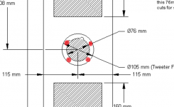
What is the correct way to mount the tweeter in the enclosure?
Is the tweeter mounted on the waveguide and then on the enclusure or they are mounted separately?
Thanks.
Is the tweeter mounted on the waveguide and then on the enclusure or they are mounted separately?
Thanks.
What is the correct way to mount the tweeter in the enclosure?
Is the tweeter mounted on the waveguide and then on the enclusure or they are mounted separately?
Thanks.
Do not mount separately. Mount the tweeter to the waveguide and then mount it, waveguide and tweeter together, as a single unit into the enclosure.
Ok, thanks to clarify.
But then i need to do room for screws on tweeter place. am i right, i didn't see those on others speaker constructions pictures.
Correct. You will need to make recesses for the nuts holding the wave guides to the speakers
Attachments
Update on Construction
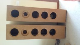
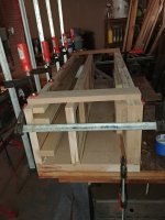
Making great progress over the past couple of weekends. Enclosures are taking shape and soon should in the prep stage prior to applying finish (paint, though thinking about veneer at this stage).
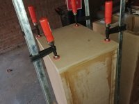
As one might see, using biscuit jointery to assemble the butt joints, except for the main brace where it is a bit more difficult to use the jointer, so just screwed and glued in place from the inside to avoid having to patch external screw holes. Also trying to avoid splitting MDF. I still have a little misalignment of the baffle to the side panels, the baffle is perhaps 0.2-0.3mm or so beyond the edge of the side panels (an artifact of the slop between the jointer in the vertical vs horizontal orientation when cutting the slots for the biscuits). If it was the other way it would be easier (planing/sanding down the edge) however now I need to patch and built back up the panel edge. Bondo time.
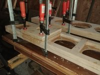
Used a neat T-nut insert designed for hardwoods for the driver mounting holes. These have short anti-rotation barbs on the barrel of the T-nut rather than spikes on the flange. Drilled out the holes to the barrel diameter, applied a bit of glue (slow setting Superglue cement) on the T-nut flange and drove them home. No splits. These do not need as large of a hole than other nut inserts, and are steel rather than zinc or brass.
David
Making great progress over the past couple of weekends. Enclosures are taking shape and soon should in the prep stage prior to applying finish (paint, though thinking about veneer at this stage).
As one might see, using biscuit jointery to assemble the butt joints, except for the main brace where it is a bit more difficult to use the jointer, so just screwed and glued in place from the inside to avoid having to patch external screw holes. Also trying to avoid splitting MDF. I still have a little misalignment of the baffle to the side panels, the baffle is perhaps 0.2-0.3mm or so beyond the edge of the side panels (an artifact of the slop between the jointer in the vertical vs horizontal orientation when cutting the slots for the biscuits). If it was the other way it would be easier (planing/sanding down the edge) however now I need to patch and built back up the panel edge. Bondo time.
Used a neat T-nut insert designed for hardwoods for the driver mounting holes. These have short anti-rotation barbs on the barrel of the T-nut rather than spikes on the flange. Drilled out the holes to the barrel diameter, applied a bit of glue (slow setting Superglue cement) on the T-nut flange and drove them home. No splits. These do not need as large of a hole than other nut inserts, and are steel rather than zinc or brass.
David
Attachments

Last edited:
Making great progress over the past couple of weekends......
David
Looks like they are coming together nicely.
I hope a locals listening session is part of your plan!
Looks like they are coming together nicely.
I hope a locals listening session is part of your plan!
Definitely part of my plan!
David
More Progress
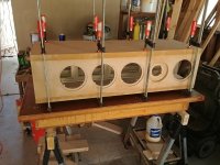
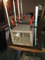
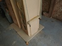
I had a little time yesterday, so glued the top and bottom on the enclosures. I made clamp extenders out of scrap MDF which were very helpful in gluing the ends on. Also, I added the damping insulation in the back corners at this time, since I figure it is easier to install with the enclosure still open. Used 1" thick bonded Dacron batting that is normally used for upholstery. It was sold as 1-1/2 to 2" thick, but the thickness was actually slightly over 1". Will see how it works.
I had a little time yesterday, so glued the top and bottom on the enclosures. I made clamp extenders out of scrap MDF which were very helpful in gluing the ends on. Also, I added the damping insulation in the back corners at this time, since I figure it is easier to install with the enclosure still open. Used 1" thick bonded Dacron batting that is normally used for upholstery. It was sold as 1-1/2 to 2" thick, but the thickness was actually slightly over 1". Will see how it works.
Attachments
Taking Shape
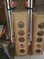
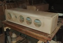
Just a quick progress post. I have the cabinets patched and edges routed to a bevel (30 deg on the baffle and 45 deg on the top and bottom side edges. I wanted to use the 30 deg bevel to help restore the baffle dimension. I used 1-1/4" (32mm) thick side panels, which would make the speaker 12mm wider. The 30 deg bevel cuts restores the front baffle width edge-to-edge. Also, I find it looks attractive. I still have to make facets at each of corners to tie in each of the bevels, but that will be work tonight.
Next comes the sealing and final sanding before painting starts.
I better get started on the crossover boards, the cabinets may be ready sooner than I expected.
David
Attachments
I used 1-1/4" (32mm) thick side panels, which would make the speaker 12mm wider. The 30 deg bevel cuts restores the front baffle width edge-to-edge.
it is worth noting that at the lower frequesncies the width of the cabinet as far as the response goes, that the bevel will not be seen and your cabinet will be seen as 12mm wider. The bevel does not achieve what you suspect. It is still good to have one IMO.
dave
Thanks for clarifying that for me. If I understand then, the baffle step based on the width will therefore start about 4% lower in frequency than the design calls for. I suspect this small increase in width might not be noticeable, but glad I did not do any more.
David
David
There are so many other variables with BSC (i rarely find it useful) that the 4% is next to nothing
dave
dave
A small bevel is not too much of a problem. What I see in the pic is about the maximum that should be OK.
Such a bevel could have an effect on the very highest frequencies, going by its size, but if the waveguide is doing its job there shouldn't be any higher frequencies on that part of the baffle.
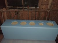
Painting and Crossover boards
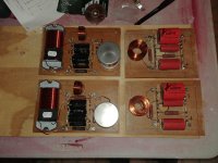
Well, progress is coming along more quickly than I expected. I have been working on prep'ing and painting the cabinets, and realized that I better get started on the crossovers. I am installing the crossovers inside the cabinet, with the tweeter crossover on the back of the tweeter brace (I already installed screw inserts to mount the crossover board), and installing the two lower bass driver crossover at the bottom of the cabinet below the drivers. The midbass crossover (single foil inductor) will be mounted to the cross brace just behind the tweeter (I have a 1/4" insert installed on the brace to bolt the inductor). The crossover boards are sized to easily fit through the bass driver holes to mounting in the cabinet, therefore are removable , and will have the wiring pre-installed with push terminals for the drivers and bare wire ends from each crossover board to a pair of binding posts on the back panel. Planning on using Cardas 15.5 ga hookup wire.
Well, progress is coming along more quickly than I expected. I have been working on prep'ing and painting the cabinets, and realized that I better get started on the crossovers. I am installing the crossovers inside the cabinet, with the tweeter crossover on the back of the tweeter brace (I already installed screw inserts to mount the crossover board), and installing the two lower bass driver crossover at the bottom of the cabinet below the drivers. The midbass crossover (single foil inductor) will be mounted to the cross brace just behind the tweeter (I have a 1/4" insert installed on the brace to bolt the inductor). The crossover boards are sized to easily fit through the bass driver holes to mounting in the cabinet, therefore are removable , and will have the wiring pre-installed with push terminals for the drivers and bare wire ends from each crossover board to a pair of binding posts on the back panel. Planning on using Cardas 15.5 ga hookup wire.
Attachments
- Home
- Loudspeakers
- Multi-Way
- The "Elsinore Project" Thread