I have attached the images here and put them into your post.
Seems to be an http: vs https: problem.
Great work, much appreciated. Joe
I had included the RTA measurement and it did not work and I still can't get it to show as an IMG link.
So you will need to click on it as a URL link.
www.customanalogue.com/elsinore/elsinore_images/EL6-MFC-OFF-AXIS.gif
Keep in mind that the below peaks and troughs are room modes and they change where you are in the room and is normal. Above 1KHz the room modes gradually become less and note how smooth the response becomes. This in fact is smoother than the NRXC.
The response below 1KHz is basically the same for both NRXC and MFC versions.
(Added it as an attachment as well.)
Attachments
Last edited:
Hi all pretty new here but I am trying to design the cuts needed to have them all cut out at a local shop that does CNC work. I think i figured out most of all the design but have one question, what is the inside diameter for the waveguide and the diameter where the curve stops before it turns to a flat disc of sorts. the waveguide is the last thing i need to model. in the mean time I will share where I am now and hopefully someone here can review my work and make sure everything is correct.
interestingly a set of 5 speakers fits well on 3 sheets of 1 inch mdf and about half a sheet of 3/4in mdf. so, the attached plans have 3 hamlets and two elsinores on them. I also made the dimensions of the internal parts 2 mm bigger and am planning on having the inside of the shell routed down by one mm on each side so they hopefully go together almost like a puzzle
interestingly a set of 5 speakers fits well on 3 sheets of 1 inch mdf and about half a sheet of 3/4in mdf. so, the attached plans have 3 hamlets and two elsinores on them. I also made the dimensions of the internal parts 2 mm bigger and am planning on having the inside of the shell routed down by one mm on each side so they hopefully go together almost like a puzzle
Attachments
I think i figured out most of all the design but have one question, what is the inside diameter for the waveguide and the diameter where the curve stops before it turns to a flat disc of sorts. the waveguide is the last thing i need to model. in the mean time I will share where I am now and hopefully someone here can review my work and make sure everything is correct.
Re the Waveguides, you do know that they are available and also buying them and using them does go a little way, not a lot, towards regaining some of the costs as even DIY is not free to the one offering it.
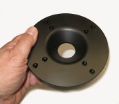
The Waveguide needs to be an incredibly close fit near the 'throat' where it sits inside the bevel next to the small surround and voice coil. If you don't get that right you can get a very erratic response in the upper octaves.
Waveguide Link - PayPal & Credit Cards
The cost is for the pair and the price for all, as it includes air freight to anywhere in the world. The declared cost will be under $100 so that customs do not get interested. I carry the insurance if it gets lost and will resend if necessary.
So there you are. 😉
Attachments

I can attest to the quality of Joe's wave guides. The fit and finish is first rate and the cost negligible in overall project terms.
I can attest to the quality of Joe's wave guides. The fit and finish is first rate.
+1, the wave guides are very well made.
I am not doubting the quality of the waveguide, just thinking that if I have this made using cnc I should be able to incorporate the waveguide into the design. However I am kinda thinking I misunderstood how the waveguide works and is connected. I was thinking that the tweeter geets mounted to the sub front panel, and the wave guide gets mounted to the front panel sitting on top of the tweeter.
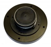
judging by the upclose photos of the wave guide, it looks like the tweeter is mounted to the waveguide and the waveguide mounted to the front panel?
judging by the upclose photos of the wave guide, it looks like the tweeter is mounted to the waveguide and the waveguide mounted to the front panel?
The original rectangular MDF waveguides (the ones I have) were mounted separately but the new ones are attached to the tweeter which becomes a single unit which is then mounted in the cabinet (preferable).
judging by the upclose photos of the wave guide, it looks like the tweeter is mounted to the waveguide and the waveguide mounted to the front panel?
That's right, they are mounted together first with the black bolts, nuts and washers (supplied). Then the waveguide with tweeter is now screwed into the sub front panel with additional black screws supplied. You will note that the front panel where the main drivers are mounted is 18mm thick, so is the waveguide, so it ends up sitting flush. The cutout is 150mm and the waveguides are 148mm diameter, so you will have a small 1mm gap all around. It all works really neat and most importantly is that it is not mechanically compromised.
While that clears some questions up it brings up others.
why not mount the tweeter/waveguide assembly directly to the front panel? wont the screws be kinda out in the open if mounted
Also being I am in the US and will probably be using 1 inch and 3/4 inch MDF sheets will there be any issues with the waveguide not being flush with the front panel?
why not mount the tweeter/waveguide assembly directly to the front panel? wont the screws be kinda out in the open if mounted
Also being I am in the US and will probably be using 1 inch and 3/4 inch MDF sheets will there be any issues with the waveguide not being flush with the front panel?
Im planning to build the Elsinore speakers and after reading the whole thread i made the crossover BOM.
Any suggestion to make best possible price performance option?
L1 3.9mH Air Core Coil 0.66 ohm 1.4mm / 15 AWG
L2 0.47mH Foil Coil 0.17 ohm 14 AWG
L3 2mH Air Core Coil 0.44 ohm 1.4mm / 15 AWG
L4 20mH Iron Core + Disc 0.93 ohm 1mm / 18 AWG
L5 0.1mH Air Core Coil 0.08 ohm 1.4mm / 15 AWG
C1 1.8uF Jantzen Superior Z-Cap
C2 33uF Jantzen Cross Cap MKP
C3 300uF Bi-polar 100V
C4 33uF Jantzen Cross Cap MKP
C? 0.47uF Audin Cap MKP Plus
R1 2 ohm Jantzen Superes Resistor 10W
R2 6.2 ohm MOX 10W
R3 9 ohm MOX 10W
R? 6.8 ohm MOX 10W
Another thing is damping material. I can get Sonofil. Is this ok? What did you fellas from Europe use?
The crossover pcbs were done on Protel and are xx.pcb files. PM me and I'll work out how to send you the files. It's split up into two pcb's. One for the tweeter and one for the 4 midwoofers. PCB manufacturers will recognise Protel files.
Just received a package from Madisound yesterday with (8) SB17MFC35-8 woofers and (2) D2608/9130 dome tweeters, so now committed and starting on the project.
Still working on the planning on my cabinets. I am finding it easier to find 18mm Baltic Birch plywood locally than 1" MDF. I did a quick beam calc comparing the two materials, taking into account that Young's Modulus for 18 mm BB is around 10 GPa with the grain of the outer veneer, and 7.5 GPa across the grain (this is from a document from the Finnish Plywood Industry). MDF has a Young's modulus of around 3.6 GPa. Anyway, the calculated stiffness for a 1 meter length with the same load distribution is virtually the same between two materials (assuming the BB outer veneer grain runs longitudinally. (i.e. 18mm BB Ply = 1" MDF). Understand that MDF has better self damping, but I think a few mm of bitumen pads should help with that.
Excited to get started, I was pretty tempted by some of Troels Gravensen's designs, but I think that a decade+ long evolutionary design and alot of builder success stories outweigh designs quickly developed (although by all appearances and builder success stories, very nice designs as well).
David
I called around and found a place that has 1" in stock in VA and takes a day to get it to any other warehouse. Its 75 a sheet. TWPerry is who it is. If you potentially want everything CNC'd PM me, I Have a buddy who's going to be doing mine once i start them.
Thanks. That is good to know. I would like to know more about the CNC arrangement, so will PM you on this. I would save alot of work.
I just finished making a press (2'x4' torsion boxes) for laminating two sheets together to achieve 1" with 1/2" material. Fortunately, I have not bought any material yet, so they can double as work surfaces for assembly.
I just finished making a press (2'x4' torsion boxes) for laminating two sheets together to achieve 1" with 1/2" material. Fortunately, I have not bought any material yet, so they can double as work surfaces for assembly.
I have had problems posting graphics from my website here, so I will try again.
The Blue is the newer MFC driver and the Red is the NRXC driver.
These measurements were taken before and after the drivers were fitted. The difference at 500Hz to 2KHz may be explained because while the exact distance was preserved, but not necessarily the exact height. So please make allowance for that - but I am pleased.
I will also add the graphic to the attachment below, in case there is a problem.
Joe R.
Attachments
Last edited:
Guys - other than some DIY drawings posted here and there in the thread and some images on Joe's site - I do not see a fully compiled dimensions, drawings, BOM, Schematic download or link for ANY version MK1 - MK6
What I am missing here? One should not have to examine 250+ pages of a thread to find the actual full build documents.
@Joe: Why not work with the moderators to edit the FIRST post in the thread to index the most important pages in this thread - where specific relevant items or changes are posted/mentioned?
Joe - I sent an email but not sure to the right mailbox:
"Pro" version with Satori drivers mentioned twice in this thread, one of them a few pages back.
Status? Worth the upgrade cost?
Hi BeanAnimal.
The construction documents are on Joe's website. The crossover is on the front page, and the cabinet drawings are linked from the index.
The construction documents are on Joe's website. The crossover is on the front page, and the cabinet drawings are linked from the index.
- Home
- Loudspeakers
- Multi-Way
- The "Elsinore Project" Thread