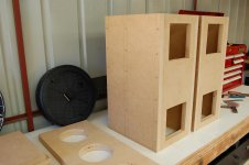
Make room for the tweeter
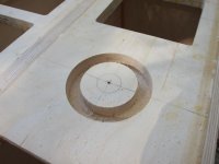
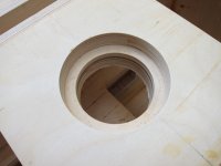
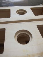
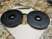
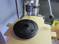
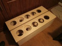
Followed the same technique on the tweeter recess as the port holes. Started with a router at 4-3/16 inch and finished with a 3-1/4 hole saw.
I made a mistake here. I was only going to recess about 5/8 inch to allow some space for threads/washers/nuts and potential gap variation. I mis-set my depth guide and dug down about 3/4 inch instead. Grrrr. Decided to clean it out to that depth and worry about fill options later.
One things for certain, I can get one hell of gap if I want too! 😱
Attachments
Tapping the waveguide...
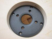
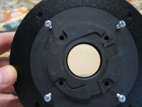
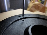
I wanted to attach the tweeter to the waveguide directly (ala Joel). However, I did not want to tap through the waveguide (I like the clean look of as few through-hole screws as possible). Basically, I wanted the attachment to be transparent. So, I used the "Joel Jig" to set the correct starting points and tapped a bit less than 5/8 inch into the waveguide. The goal was to get a minimum of 1/2 inch of solid threads to hold the tweeter tight.
I used a technique passed on to me from a very wise man whereas you use a taper tap to set the first few threads and then follow up with a plug tap to set the rest of the threads. Ideally, you finish with a bottom tap, but, I do not have one at the 6-32 size, so, I am missing an extra thread or two the bottom tap would have provided.
After drilling the pilot hole with a drill press, I used a taper tap mounted in the drill press (but NOT POWERED by the drill press) to start the tap. The use of some form of jig or press is key as it insures the tap is straight from the start and not off-center (which, if off-center, yields all kinds of problems). The tap is mounted in the press and used with the power OFF (VERY important). You hand turn the chuck while applying steady pressure with the feed handle. This is only done for the first few threads, after which, I backed off and switched to a hand-held plug tap to finish the job. Lot's of cutting oil and textbook tap technique to be sure the tap does not bind nor break. Worked great! A quick test verified the taps were long enough and the tweeter face plate centered.
Hard to find cut-to-fit 6-32 thread, so, I cut the tops off of some 1 inch 6-32 screws with a Dremel and set them into the waveguide.
Sweet. Time to mount the tweeter itself.
Attachments

Nice and tight...
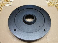
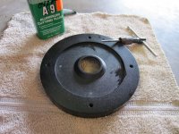
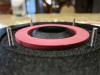
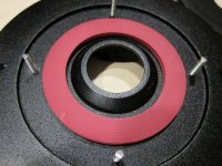
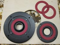
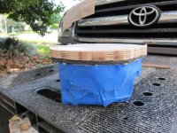
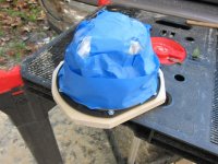
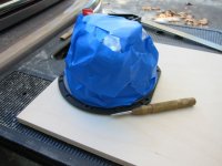
Since I have the recessed version of the waveguides, I wanted to seal the tweeter front panel solid against the waveguide.
I looked around and settled on using a rubber washer I found at Home Depot intended for a Toilet Flush Valve Seal. 😀
These are only about 1/16 of an inch thick, so, two are needed to be tight enough to compress and form a complete seal. The OD is just about perfect. I had found 1/8 inch seals, but, the OD was too small to make a clean fit and they did not compress as well as the two smaller seals.
These will do just fine.
Attachments
Great idea, I was just going to fill mine with duct seal, but this seems like a much better approach.
Thanks!
Many thanks for sharing your journey and good ideas with the rest of us.
I like the seals a lot and will incorporate in my very slow build.
Francois
Since I have the recessed version of the waveguides, I wanted to seal the tweeter front panel solid against the waveguide.
I looked around and settled on using a rubber washer I found at Home Depot intended for a Toilet Flush Valve Seal. 😀
These are only about 1/16 of an inch thick, so, two are needed to be tight enough to compress and form a complete seal. The OD is just about perfect. I had found 1/8 inch seals, but, the OD was too small to make a clean fit and they did not compress as well as the two smaller seals.
These will do just fine.
Many thanks for sharing your journey and good ideas with the rest of us.
I like the seals a lot and will incorporate in my very slow build.
Francois
Parts Express has the Peerless 6 1/2" driver as deal of the day today. About $10 off. Nov 11, 2011.
Meanwhile on the cabinet front...
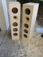
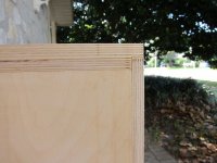
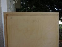
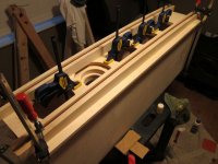
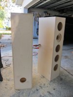
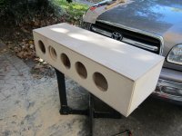
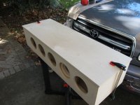
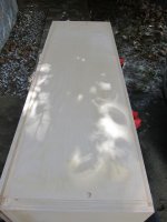
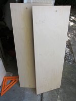
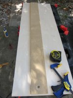
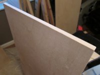
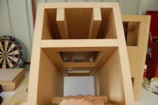
Aligned and glued on the front panel and final top layer using the previously discussed clamping techniques. I left overlap on both panels as well, which was trimmed down with the router. This worked well once again.
The seams/layers of the front panel and top panel can be seen on the pics below. These seams will be completely hidden once the final side pieces are mounted. The miter turned out okay. Not perfect, but, acceptable.
The side panels (the final pieces to the cabinet) are going to be finished differently from the rest of the cabinet, so, I need to come up with a technique that aligns them for fitting and trimming yet allows me to remove them for finishing before the final glue down. I have some ideas on how to proceed. We shall see how they work.
Anyway, really starting to take shape (finally!). Might enter them in the "most overbuilt cabinet" contest. 😉
Attachments

Hi Guys
I have a guy in Denmark who has emailed me. Is there anybody who has built Elsinores and that he could have a listen, as he is keen to build but would like to hear them first. So any Danish builders who can help?
Cheers, Joe R.
I have a guy in Denmark who has emailed me. Is there anybody who has built Elsinores and that he could have a listen, as he is keen to build but would like to hear them first. So any Danish builders who can help?
Cheers, Joe R.
Sizing the side panels...
Lot's to be thankful for including beautiful Florida weather!
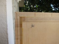
As mentioned previously, I wanted to have the side panels be trimmed to fit like all the previous panels, yet, still detachable to allow me to apply their finish separate from the main part of the cabinets. Once finished, I will glue them onto the main part of the cabinet. The challenge was how to maintain alignment?
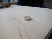
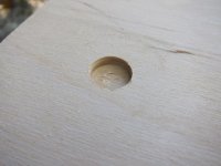
I decided to go with a shallow, dowel-like technique. The thought was to ensure alignment of the pieces without making too big a physical impact to the side panels nor the main cabinets.
So, using 1/4 birch flat end-plugs, I created a dowel-like attachment system. The nice thing about the plugs is they only have to penetrate about two or three plys into the material (alignment, not strength). They are also easy to size for a hole as a 1/4 inch router bit on a plunge base worked perfect while still being controllable. Since the plugs are tapered, they had to be slightly sanded to make the fit work. The plugs were placed into the side panel (using a rubber mallet and a small amount of glue to force and retain the plug in the hole). Alignment between the surfaces was maintained by the use of a simple jig. The placement of the holes was off-center aligned with the center brace of the main cabinet. This ensures they only go on one way (although they are labeled as well) and puts the dowel on the strongest part of the cabinet. A bit of finesse trimming for depth and fit and we are in business. Used the flush trim bit again to fit the panels onto the main cabinet.
At this point, the main cabinet cutting/construction is complete. Now to make it look pretty. 😀
Lot's to be thankful for including beautiful Florida weather!
As mentioned previously, I wanted to have the side panels be trimmed to fit like all the previous panels, yet, still detachable to allow me to apply their finish separate from the main part of the cabinets. Once finished, I will glue them onto the main part of the cabinet. The challenge was how to maintain alignment?
I decided to go with a shallow, dowel-like technique. The thought was to ensure alignment of the pieces without making too big a physical impact to the side panels nor the main cabinets.
So, using 1/4 birch flat end-plugs, I created a dowel-like attachment system. The nice thing about the plugs is they only have to penetrate about two or three plys into the material (alignment, not strength). They are also easy to size for a hole as a 1/4 inch router bit on a plunge base worked perfect while still being controllable. Since the plugs are tapered, they had to be slightly sanded to make the fit work. The plugs were placed into the side panel (using a rubber mallet and a small amount of glue to force and retain the plug in the hole). Alignment between the surfaces was maintained by the use of a simple jig. The placement of the holes was off-center aligned with the center brace of the main cabinet. This ensures they only go on one way (although they are labeled as well) and puts the dowel on the strongest part of the cabinet. A bit of finesse trimming for depth and fit and we are in business. Used the flush trim bit again to fit the panels onto the main cabinet.
At this point, the main cabinet cutting/construction is complete. Now to make it look pretty. 😀
Attachments
-
 IMG_3332.jpg50.4 KB · Views: 260
 -
 IMG_3327.jpg59.9 KB · Views: 207
 -
 IMG_3324.jpg53.4 KB · Views: 192
 -
 IMG_3321.jpg40.9 KB · Views: 168
 -
 IMG_3320.jpg45.4 KB · Views: 159
 -
 IMG_3317.jpg36.4 KB · Views: 163
 -
 IMG_3316.jpg25.4 KB · Views: 151
 -
 IMG_3315.jpg38.7 KB · Views: 163
 -
 IMG_3314.jpg49.5 KB · Views: 302
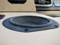
Big decision point, to flush mount or not to flush mount...
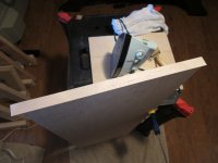
Surprisingly, a tricky question for me. I went ahead and test mounted one of the drivers without flush mounting and much to my surprise, I liked the way it looked. A much better look than I thought it would be. Kind of gives the baffle a more dimensional look. So, at this point, I am not sure what I am going to do.
In any case I went ahead and made a flush mount template to give me options. What I should have done is followed this EXACTLY:
Flush Mounting an Irregular Baffle
But no, I had to get clever. I honestly thought I could do it with less material waste. What an incorrect thought that turned out to be!
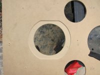
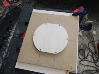
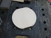
But, my technique worked, so, it could be worse I suppose. I first protected the driver and using a flush trim bit, made an exact copy of the driver shape. I figured this would buy me a margin of safety in case I need to make repeated attempts. The goal was to minimize actual use of the driver if at all possible. You can tell by the scorch marks, my flush trim bit is on it's last legs. Once I had the basic shape, it was just a matter of tracing the template(s).
This is where I miscalculated the frugality of my approach. While my technique can use smaller pieces of material for the initial cut, it requires four steps vice the three in the link above.
- First, trace the shape with a 3/8inch bushing
- Second, use the resulting template and cut another using a 1/2inch bushing
(This makes the pre-template for cutting the actual templates)
- Third, use the resulting intermediate (or pre-template) and cut the "final" template using a 1/2inch bushing
- Fourth, use the final template with a 3/8inch bushing to route the recess for the driver.
The first cut adds 7/8inch to the shape. The next two subtract 1/4inch from each template to account for the width of the router bit. The final removes the 3/8inch extension incurred by the first bushing. The result is a match of the initial shape. The result is only as good as the initial driver tracing, so, care has to be exercised at all steps, but especially getting the shape right in the first place.
I enclosed some pics of the process. The test fitting looked fine. Slightly snug. I had to lightly sand the recess sides to get a clean, smooth fit, but, it looks pretty close to me. No real deviations from the actual shape itself. At this point, I just need to make a centering device to insure template alignment is maintained if and when I make the final recesses on the cabinet itself.
Decisions, decisions, decisions....
Surprisingly, a tricky question for me. I went ahead and test mounted one of the drivers without flush mounting and much to my surprise, I liked the way it looked. A much better look than I thought it would be. Kind of gives the baffle a more dimensional look. So, at this point, I am not sure what I am going to do.
In any case I went ahead and made a flush mount template to give me options. What I should have done is followed this EXACTLY:
Flush Mounting an Irregular Baffle
But no, I had to get clever. I honestly thought I could do it with less material waste. What an incorrect thought that turned out to be!
But, my technique worked, so, it could be worse I suppose. I first protected the driver and using a flush trim bit, made an exact copy of the driver shape. I figured this would buy me a margin of safety in case I need to make repeated attempts. The goal was to minimize actual use of the driver if at all possible. You can tell by the scorch marks, my flush trim bit is on it's last legs. Once I had the basic shape, it was just a matter of tracing the template(s).
This is where I miscalculated the frugality of my approach. While my technique can use smaller pieces of material for the initial cut, it requires four steps vice the three in the link above.
- First, trace the shape with a 3/8inch bushing
- Second, use the resulting template and cut another using a 1/2inch bushing
(This makes the pre-template for cutting the actual templates)
- Third, use the resulting intermediate (or pre-template) and cut the "final" template using a 1/2inch bushing
- Fourth, use the final template with a 3/8inch bushing to route the recess for the driver.
The first cut adds 7/8inch to the shape. The next two subtract 1/4inch from each template to account for the width of the router bit. The final removes the 3/8inch extension incurred by the first bushing. The result is a match of the initial shape. The result is only as good as the initial driver tracing, so, care has to be exercised at all steps, but especially getting the shape right in the first place.
I enclosed some pics of the process. The test fitting looked fine. Slightly snug. I had to lightly sand the recess sides to get a clean, smooth fit, but, it looks pretty close to me. No real deviations from the actual shape itself. At this point, I just need to make a centering device to insure template alignment is maintained if and when I make the final recesses on the cabinet itself.
Decisions, decisions, decisions....
Attachments
-
 IMG_3353.jpg39.2 KB · Views: 252
 -
 IMG_3352.jpg54.9 KB · Views: 242
 -
 IMG_3350.jpg52.2 KB · Views: 242
 -
 IMG_3345.jpg45.2 KB · Views: 218
 -
 IMG_3343.jpg49.8 KB · Views: 213
 -
 IMG_3341.jpg61.4 KB · Views: 221
 -
 IMG_3340.jpg79.1 KB · Views: 223
 -
 IMG_3339.jpg59.4 KB · Views: 205
 -
 IMG_3336.jpg46.8 KB · Views: 271
 -
 IMG_3359.jpg50 KB · Views: 254
Really nice work! I'm looking forward to seeing them finished. Thanks for taking the time to post all your trial and tribulations and this project. I think kit this is what I'm going to build eventually for my "dream" speakers.
Thanks. I am looking to see them finished myself! 😀
BTW, I've been to Skycraft more than a few times. Have not been there in many years though. Hope it has not changed a bit!
BTW, I've been to Skycraft more than a few times. Have not been there in many years though. Hope it has not changed a bit!
Seldom (if ever) used domestic skills in the service of a higher cause...
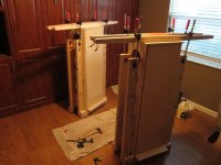
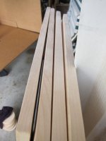
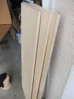
Well, I managed to locate and blow the dust from our lonely clothes iron and went ahead and applied edge banding to the side panels. Easy as pie, even from someone who believes whole-heartedly in permanent-press and wash and wear.
Very forgiving material. If you make a mistake, just heat it up, remove it and start with a new piece. Once applied, trim it close using a razor-based plastic edge trimmer. The trimmer works fine once you get the hang of it. Final edge is put on with a light sanding.
Of note, I miscalculated the amount of edge banding I would need. So, I ended up using my veneersupplies.com "premium" banding on the front/top surfaces and used a lesser grade (available locally from lowes) on the back. This will be an interesting experiment to see if the edge telegraphs through the material as the veneersupplies banding is much, much thicker.
Anyway, cleaned up and sanded down the boards and moved them into position for painting and drying using my no-expense-spared custom paint chamber. 😉
Attachments


jdkjake, just a word about recess mounting the woofers, It will change the setback distance between the woofer and tweeter and how the woofer interacts with the cabinet. I don't know how much it will affect the sound.
jdkjake, just a word about recess mounting the woofers, It will change the setback distance between the woofer and tweeter and how the woofer interacts with the cabinet. I don't know how much it will affect the sound.
Thanks for the heads-up tpate. The effects of the flush mounting the mid/bass drivers have been discussed once or twice over the life of the thread. I believe the last time Joe chimed in on the topic was post 95. There he stated the effects would be minimal.
The main reason to flush mount IMHO is purely aesthetic. At this point, I am still not sure what I am going to do as the asthetics using surface mounting is pretty nice as well. I will make the final decision once I finish the veneering of the main part of the cabinet. That is dragging out a bit as I experiment with a couple different veneers and various finishes.
Thanks again for the caution.
Veneer and stain and finishes... OH MY!!
Decisions, decisions, decisions.
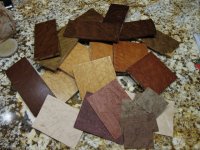
Made test presses of a couple different veneers with multiple variations of stain and finish options.
I think a decision has been made (finally).
Big thanks to Joel for talking me into using raw wood veneer! Amazing results, even with just test pressings.
BTW, ignore any pressing errors you see. This was more about color testing than press testing. All of my test presses have turned out just fine. 🙂
Decisions, decisions, decisions.
Made test presses of a couple different veneers with multiple variations of stain and finish options.
I think a decision has been made (finally).
Big thanks to Joel for talking me into using raw wood veneer! Amazing results, even with just test pressings.
BTW, ignore any pressing errors you see. This was more about color testing than press testing. All of my test presses have turned out just fine. 🙂
Attachments
Decisions, decisions, decisions.
Made test presses of a couple different veneers with multiple variations of stain and finish options.
I think a decision has been made (finally).
Big thanks to Joel for talking me into using raw wood veneer! Amazing results, even with just test pressings.
BTW, ignore any pressing errors you see. This was more about color testing than press testing. All of my test presses have turned out just fine. 🙂
Glad you like Raw wood veneer without a backing. I'ts addictive material.
Have you tried Dissolved shellac as a finish? Very natural and can make them as beautiful as a fine guitar. Mind you I'm still working on the final aspect to complete the finish..
Glad you like Raw wood veneer without a backing. I'ts addictive material.
Have you tried Dissolved shellac as a finish? Very natural and can make them as beautiful as a fine guitar. Mind you I'm still working on the final aspect to complete the finish..
I gotta tell you, I am totally sold on raw wood veneer. Just have to deal with the occasional hole to prevent excessive glue leak-through. Other than that, well, the world is your oyster. Anything is possible.
Right now, I am using water-based, oil-modified polyurethane finish in both satin and semi-gloss. Nice results in three or four coats with little to no fumes.
I did a little reading on shellac finishes as well as using Boiled Linseed Oil to bring out the figure prior to finish. Probably a step or two beyond this project at this point. Heck, it took three weeks, two veneers, five stains (with eight separate variations/mixes) and two finishes to get this far. Not sure I can handle any more choices/methods at this point!! 😉
Perhaps the next build. In the meantime, I look forward to your results using shellac. There is something quite enticing about using classic, natural methods and finishes.
Did some more work on the hamlets today.
Looking GREAT spoonted!!
BTW, what method did you use to perform the cutouts on the center brace? They look amazing.
- Home
- Loudspeakers
- Multi-Way
- The "Elsinore Project" Thread