I do not want to pollute Joe's thread, but unfortunately none of the promised secrets are revealed in the link https://jrkpost.medium.com/loudspeakers-the-secrets-of-distortion-cf24473c8be. As it seems, it is al about the ongoin quest for flattening the BL vs Excursion curve. That might have been said in less vague language. Furthermore, the shift to ceramic magnets started in the sixties, not in 1978. Apart from exotics (Lowther, expensive JBL's etc.), in 1978 you could hardly buy any AlNico drivers. Virtually all then generally available KEF, Audax, Philips, Seas, Goodmans etc, Heco, Peerless used ceramic magnets.
Hello,I do not want to pollute Joe's thread, but unfortunately none of the promised secrets are revealed in the link https://jrkpost.medium.com/loudspeakers-the-secrets-of-distortion-cf24473c8be. As it seems, it is al about the ongoin quest for flattening the BL vs Excursion curve. That might have been said in less vague language. Furthermore, the shift to ceramic magnets started in the sixties, not in 1978. Apart from exotics (Lowther, expensive JBL's etc.), in 1978 you could hardly buy any AlNico drivers. Virtually all then generally available KEF, Audax, Philips, Seas, Goodmans etc, Heco, Peerless used ceramic magnets.
When I hear that someone say that they have secrets. I pucker up a bit and prepare for the sales pitch.
Take a look at this link for as far as I can tell is one of the straight foreword sources of speaker distortion information. Purifi Blog information is not bad either.
https://www.klippel.de/fileadmin/_m...linearities–Causes_Parameters_Symptoms_01.pdf
Thanks DT
Hello DT,
In another thread yesterday the same link popped up. https://www.diyaudio.com/community/threads/the-birth-of-a-15-inch-woofer.341825/page-5#post-6716153
In a somewhat differently phrased response I referred to both Klippel and Lars Risbo myself. Good to know we are on the same page.
Thanx anyway!
In another thread yesterday the same link popped up. https://www.diyaudio.com/community/threads/the-birth-of-a-15-inch-woofer.341825/page-5#post-6716153
In a somewhat differently phrased response I referred to both Klippel and Lars Risbo myself. Good to know we are on the same page.
Thanx anyway!
Experiments done by me and others don't show current drive to produce less distortion per se.
So true.
I have been thinking about answering the point you made and perhaps a bit late as it is now days ago since you said the above.
I am glad that you have done those tests yourself and that you found it produces produces lower distortion. There are now a number of examples that have been posted on the internet. Pavel (PMA) has and I tried making an approach, but he knocked me back. I don't doubt the measurements, but I doubt the interpretations.
We agree that the differences are definitely there. But what is this lower distortion? Or maybe we are looking at it the wrong way around?
Sometimes the wrong questions are asked and then nobody asks the right question?
This has reverberated in my head for more than ten years. Will we ever make progress? Do you that we often have to get things down to the most basics, which I did. The it dawned on me, read the next sentence very carefully, please.
What will show we are making the correct progress? Here I want to make a point that requires a LOT of lateral thinking:
This is what hit me:
We know we are making real progress when we get the same or near low distortion with both current and voltage drive.
Please, think about it.
We need the same low distortion from voltage drive that we can get from current drive.
IN A PERFECT WORLD WHAT DOES THAT REQUIRE?
The answer, although difficult to achieve, is actually simple?
I have the answer, but what do you think it is?
THE ANSWER IS A BEAUTY!
I will give you a significant clue," current drive does not reduce the distortion of the driver. It might look that way, and I suspect this is also Esa's view. The answer to the question shows that is not the case.
Over to you.
Once again, what would it require to have the same low distortion with voltage drive that current drive is capable of?
In theory the answer is simple and yet surprising. And yet it also helps us to understand where to go next.
Attachments

The real test is whether a voltage driven amp that is loaded not only by a driver, but also by a number of LCR conjugate networks to tame and turn the impedance peak into say 8 Ohms resistive (like the Elsinore woofer leg), will display higher distortion than an equally loaded (+same woofer) current amp. Maybe yes, maybe no: dunno: I am not aware of any testing of that kind.
So true.
I have been thinking about answering the point you made and perhaps a bit late as it is now days ago since you said the above.
I am glad that you have done those tests yourself and that you found it produces produces lower distortion. There are now a number of examples that have been posted on the internet. Pavel (PMA) has and I tried making an approach, but he knocked me back. I don't doubt the measurements, but I doubt the interpretations.
We agree that the differences are definitely there. But what is this lower distortion? Or maybe we are looking at it the wrong way around?
Sometimes the wrong questions are asked and then nobody asks the right question?
This has reverberated in my head for more than ten years. Will we ever make progress? Do you that we often have to get things down to the most basics, which I did. The it dawned on me, read the next sentence very carefully, please.
What will show we are making the correct progress? Here I want to make a point that requires a LOT of lateral thinking:
This is what hit me:
We know we are making real progress when we get the same or near low distortion with both current and voltage drive.
Please, think about it.
We need the same low distortion from voltage drive that we can get from current drive.
IN A PERFECT WORLD WHAT DOES THAT REQUIRE?
The answer, although difficult to achieve, is actually simple?
I have the answer, but what do you think it is?
THE ANSWER IS A BEAUTY!
I will give you a significant clue," current drive does not reduce the distortion of the driver. It might look that way, and I suspect this is also Esa's view. The answer to the question shows that is not the case.
Over to you.
Once again, what would it require to have the same low distortion with voltage drive that current drive is capable of?
In theory the answer is simple and yet surprising. And yet it also helps us to understand where to go next.
Hello Joe,
As you know, you are not saying anything. There is no news.
What driver are you speaking of? Where is the data?
Are talking about your new reference driver or a Purifi driver?
For grins here are impedance and phase plots for the Scanspeak and Purifi drivers. At 2 volts input.
Thanks DT
As you know, you are not saying anything. There is no news.
Meaningless statement. And I don't know what you are saying either.
It's not about news. That's missing the point entirely... again.
It's a question:
Why can't we get the low distortion of current drive when using voltage drive?
I don't think that current drive is the answer.
It is about something better because it is far more practical:
What can we do to make voltage drive have lower distortion and sound like current drive.
Practical, not theory, outcomes and solutions are what interests me, not endless banter that gets us nowhere.
Again, look at the Elsinore design. I have listed six things about the design that gives me what?
LOWER DISTORTION!
That is what I want. That is the only question and not endless theory.
Yes, the Elsinores sound always more like current drive even when the amplifier is a voltage source. On top of that, even if you insist on current drive, they will work with them as well. They will work with any amplifier and I have posted that proof many times:
ABOVE: ELSINORE ULD 15° OFF AXIS
And it is all to do with those six things I have listed. Practical outcomes, solutions that work, not news, not olds, not whatever that is supposed to mean (nothing really).
Below I have reposted what they are:
1. Select the right driver(s). Forget current-drive making it better, even current-drive cannot do that.
2. If available, use multiple drivers to reduce excursions. At mid frequencies, cone motion is a problem with most drivers, and using multiple drivers gives you a potential advantage and hence lower distortion.
ABOVE: ELSINORE LF LINE SOURCE GETS CLOSER TO PURIFI.
3. Equalise, or EQ the current and make the load virtually non-reactive and look like a resistor. The current phase angle will always be near zero.
4. On the low-pass filter add an external inductor to reduce/Stabilise impedance/current modulations. If you add three times the inductance, you can get major stabilising of the inductive impedance shown below and lowers distortion.
ABOVE: IMPEDANCE IS NOT STABLE, EVEN IF WE THINK IT IS, AND CAUSE CURRENT MODULATIONS IN THE AMPLIFIER = DISTORTION.
5. Use a waveguide, this time on the tweeter. This allows you to use a much smaller value series capacitor that increases the series reactance in the high-pass. In the Elsinores, we end up around 30 Ohm, plus near 10 Ohm at the load and 40 Ohm in total. Effectively you are now using a form of current drive.
6. Make the tweeter produce virtually zero amplitude (no piston movement), use an LC notch filter tuned to the Tweeters resonance, which should be 2+ Octaves below the crossover frequency.
All the above techniques have been optimised in the Elsinores. They all reduce measured distortion and the reasons are obvious.
The Elsinore sounds virtually like current-drive when using voltage-drive.
Please note that the above six are only briefly summarised. The detail of execution is also important.
What is the difference between the above points 3 and 4? Zobel for North of 500 Hz, triple conjugate for LF, i.e. DC to 500.
What is the difference between the above points 3 and 4? Zobel for North of 500 Hz, triple conjugate for LF, i.e. DC to 500.
OK, you may be coming in late in the discussion. To understand the difference between 3. and 4. read this earlier post, link below, and let me know if you understand it. I hope so because only one so far here has come back and expressed they understood it.
Link to Post #4912
Hello Joe,
If you are looking for practical solutions to reducing and testing distortion in your Scanspeak reference driver consider this impedance compensation. Amplifiers and crossover networks like flat impedance curves much better (lower distortion).

This graphic was lifted from a 2020 AudioExpress.
https://audioxpress.com/article/voice-coil-lab-notes-improved-zobel-network
The original work was done by W. MARSHALL LEACH, JR. in 2000 and published in an AES paper in 2004.
https://www.aes.org/tmpFiles/elib/20220901/12997.pdf
Things work out better when signal levels are kept Small. Crank things up and variable BL and Le become problematic.
Thanks DT
The APx 500 software will calculate L2 and R2 to use to calculate capacitors and Resistors for the improved Zobel if you like.
If you are looking for practical solutions to reducing and testing distortion in your Scanspeak reference driver consider this impedance compensation. Amplifiers and crossover networks like flat impedance curves much better (lower distortion).
This graphic was lifted from a 2020 AudioExpress.
https://audioxpress.com/article/voice-coil-lab-notes-improved-zobel-network
The original work was done by W. MARSHALL LEACH, JR. in 2000 and published in an AES paper in 2004.
https://www.aes.org/tmpFiles/elib/20220901/12997.pdf
Things work out better when signal levels are kept Small. Crank things up and variable BL and Le become problematic.
Thanks DT
The APx 500 software will calculate L2 and R2 to use to calculate capacitors and Resistors for the improved Zobel if you like.
Last edited:
If you think you are smart enough, publish your own design and create a new thread (not sporadically post your thought here) and see how many member build your design. no need to critisize someone else design that is already matured, you don't agree with Joe's approach then leave this thread. nobody ask you to chime in anyway 🙂Hello Joe,
If you are looking for practical solutions to reducing and testing distortion in your Scanspeak reference driver consider this impedance compensation. Amplifiers and crossover networks like flat impedance curves much better (lower distortion).
again, again, and again same story with someone new to this thread act like he is so smart..pfffeuhhhhh
Perhaps he has the idea this is a thread on a discussion forum and not an authocracy?If you think you are smart enough, publish your own design and create a new thread (not sporadically post your thought here) and see how many member build your design. no need to critisize someone else design that is already matured, you don't agree with Joe's approach then leave this thread. nobody ask you to chime in anyway 🙂
again, again, and again same story with someone new to this thread act like he is so smart..pfffeuhhhhh
Nobody asked You to chime in anyway.😀
Joe, let’s say for a minute you’re onto something here with this current drive thing and the amp should see a linear load (I’m not disagreeing with you) - is there possibly a solid state approach to the phase and impedance correction you could use, like active power factor correction etc?
Hello @mainframe99,Joe, let’s say for a minute you’re onto something here with this current drive thing and the amp should see a linear load (I’m not disagreeing with you) - is there possibly a solid state approach to the phase and impedance correction you could use, like active power factor correction etc?
After looking at Joe’s design and the many posts in this thread I get the impression that Joe expects most users will be using off the shelf amplifiers and current equalization networks made up from a box of passive parts.
If you look at the Esa Merilainen book it is full of active equalization circuits to do just what you said.
I believe that you are on target speaking of power factor correction as a practical solution.
The Marshall Leach solution I offered up a couple of posts ago is a couple of capacitors and resistors that make a Zobel that is in parallel with the resistive inductive driver load. The phase angle of the RC Zobel is opposite to the phase angle of the inductive driver load. This is very much like your local power utility switching in a bank of capacitors for power factor correction.
Marshall Leach calculated the 2 capacitor + 2 resistor Zobel to flatten the impedance curve of the resistor + inductor load of the driver. The impedance curve ends up being pretty much flat.
Thanks DT
Hello Gadut,If you think you are smart enough, publish your own design and create a new thread (not sporadically post your thought here) and see how many member build your design. no need to critisize someone else design that is already matured, you don't agree with Joe's approach then leave this thread. nobody ask you to chime in anyway 🙂
again, again, and again same story with someone new to this thread act like he is so smart..pfffeuhhhhh
I do no suppose that you have noticed.
I have not criticized Joe’s designs nor have I posted any design of my own. Please list the posts where I have criticized Joe’s designs.
I do like Joe’s approach; in fact I spoke of him as more of an artist than a textbook jockey. I would like to see more about how Joe does his distortion measurements. I also would like to see the Scanspeak P17WJ 00 08 driver test results that he has been going on about.
A couple of posts ago Joe asked for thoughts or practical ideas about how to reduce distortion in a voltage source and make it perform like a current source. I thought that Joe may have been asking for simple ideas about how to configure and test his new reference driver. I offered Marshall Leach’s 2 resistor 2 capacitor Zobel as a possible solution. I have not seen that simple Zobel soultion in this thread or in the Esa Merilainen book.
You took that as criticism of Joe’s design, which it was not. Thank you very much.
Thanks DT
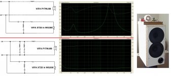
Coincidentally, I'm tuning a speaker crossover with a VIFA 17PWJ08. I'm reading a claim from Joe Rasmussen here about increasing distortion in voltage amplifiers due to load impedance swings. I was always mainly interested in practice, what I hear or don't hear. That some measurement will show a difference is one thing, what the ear perceives and the brain is another and more important thing. So I decided to do a listening test of the effect of including compensation, I have a transistor amplifier. The imbalance without compensation is really big with my speakers, the maximum of 2.8kHz is over 100 Ohm. The crossover is located on the cabinet, so it is easy to quickly engage and disengage the compensations. I noticed only a small change in the sound, with the compensations the micro-detail decreased a bit, the experience became darker. The difference is really small. I hear a much bigger change in sound when I change the power cable to the amplifier.
When using an amplifier with a high output impedance (tubes), the compensation of the speaker impedance is good, but there is a significant effect on the frequency response, and this makes more audible differences in speakers with unbalanced impedance, such as my case. I'm sorry for my bad English.
When using an amplifier with a high output impedance (tubes), the compensation of the speaker impedance is good, but there is a significant effect on the frequency response, and this makes more audible differences in speakers with unbalanced impedance, such as my case. I'm sorry for my bad English.
Attachments
Pandinus, would you care to share summed and indiviual responses (W and T) of both combo's? Nearfield LF measurements for both versions is also of great interest.
Coincidentally, I'm tuning a speaker crossover with a VIFA 17PWJ08. I'm reading a claim from Joe Rasmussen here about increasing distortion in voltage amplifiers due to load impedance swings. I was always mainly interested in practice, what I hear or don't hear.
No, that is incorrect, I think you have misuderstood something.
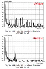
Indeed I have a pair of Vifa drivers here and they are an example of a driver I do not want to use for design purposes. To me it is a reference for what I do not want a driver to do. Yeah, I know, it's complicated. I use it to measure distortion in amplifiers on the current side. I want an imperfect driver for that. I am not going to use it in a project. To me it is a reference driver.
But I don't want to discourage, good to see hands-on DIY.
Did you also measure frequency response? The change you heard was most probable due to a slight FR change.Coincidentally, I'm tuning a speaker crossover with a VIFA 17PWJ08. I'm reading a claim from Joe Rasmussen here about increasing distortion in voltage amplifiers due to load impedance swings. I was always mainly interested in practice, what I hear or don't hear. That some measurement will show a difference is one thing, what the ear perceives and the brain is another and more important thing. So I decided to do a listening test of the effect of including compensation, I have a transistor amplifier. The imbalance without compensation is really big with my speakers, the maximum of 2.8kHz is over 100 Ohm. The crossover is located on the cabinet, so it is easy to quickly engage and disengage the compensations. I noticed only a small change in the sound, with the compensations the micro-detail decreased a bit, the experience became darker. The difference is really small. I hear a much bigger change in sound when I change the power cable to the amplifier.
When using an amplifier with a high output impedance (tubes), the compensation of the speaker impedance is good, but there is a significant effect on the frequency response, and this makes more audible differences in speakers with unbalanced impedance, such as my case. I'm sorry for my bad English.
//
- Home
- Loudspeakers
- Multi-Way
- The "Elsinore Project" Thread