Out of stock...does anyone know if that's a permanent thing or temporary. Sometimes kits just go away. Looks like a fun project though.
It's so popular that I have to think it will be in stock again, and it only seems to be some of the parts.
I'd ask here first:
Amp Camp Amp Kit V1.6
Here is the original thread:
Amp Camp Amp - ACA
Last edited:
Note: IF you go with a Line Magnetic Audio product (Joe mentioned) - make sure it's a proper 110v/60 Hz design (for US), which usually requires an importer like Tone Imports.
The 211iA is cheap with the 220-240v design:
Line Magnetic Audio LM Tube Amplifier : China-hifi-Audio online store, Yaqin,Meixing Mingda,XiangSheng,Line Magnetic Tube Amplifier, power amp, preamp,hi-fi CD Player high end audio for sale
(..not really fond of the 12ax7 preamp.. but for a LOT more money the LM-508IA looks "juicy".)
Last edited:
I just found the Elsinore website Elsinore End Game
There are a bunch of measurements, including an outdoor acoustic measurement of a 700 Hz square wave. Looks pretty decent to me.
There is also a note about the 5 dB hump at 150 Hz, saying that it's due to the microphone proximity effect. I don't quite understand this. I thought that this effect does not happen with typical measurement microphones. This comment also seems to imply that the low frequency part of the SPL curve was measured in the free field, where the room controls the low frequency response. Also, a very long time window would be required to obtain such low frequency data, which in turn would mean that the full SPL curve is NOT anechoic.
Joe: how did you determine the SPL curve? Can you upload the impulse response or the step response data?
It's so popular that I have to think it will be in stock again, and it only seems to be some of the parts.
The ACA has gone in & out of stock quit often as people have come to realize how good an amplifier is.
Be patient.
dave
The ACA has gone in & out of stock quit often as people have come to realize how good an amplifier is.
Be patient.
dave
Appreciate that...several kits for sale in the Swap Meet section. No familiar with the kit enough to know if buying an assembled kit on the Swap Meet is a good idea or no.
I have been chasing transient perfect speakers for their super recreation of minimally post-processed live recording of drums and jazz ensembles.
Thanks in advance.
X
Assuming I understand your 'transient perfect' speaker description correctly, then I would certainly say that the Elsinore qualifies.
The reversed tweeter in the schematic can be confusing. At the very beginning I got some unpleasant emails that accused me of fooling people. Finger wagging at me, they, of course, were NOT fooled. But in reality I was not wishing to mislead anybody.
So I wrote a 'paper' that I could point to, that a tweeter with infinite rise time is actually an acoustic inverter. The agrument made is a very tight one and that got a few monkeys of my back.
Of course, there is no such a tweeter, no driver has a totally instant rise time. It takes time take to go from A to B. So depending on the input power level, below a certain frequency it would invert and above it, it would follow the electrical input response. Generally, four times the power and the frequency would be halved. I chose 4 Watt (a decent amount of power for a tweeter) and provided that frequency does not drop below 10KHz, then for 1 Watt it would be 20KHz.
You can read the two articles here:
JR Approach to Crossovers
And:
The Renegade Tweeter Theory
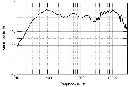
For those interested in the step response, here are a couple of excerpts:
Except for quite high frequencies, the impulse response goes upwards.
Note that you can see the reverse phase at high frequencies if you know what to look at, but the overall square wave is maintained as this is 2 metres away and the air acts as a low pass.
Why go to all this trouble? Because if you put the drivers in the same phase, the step response only exists over a very narrow area, go left or right, up or down (relative to the tweeter) then it goes awry. This indicates poor power response (of axis response lacking) and so on. The reason is explained by the fact that -3dB summing for a perfect, and narrow window, step response means that half the output at the crossover frequency gets canceled out. But reverse the tweeter electrically, take advantage of its natural inclination to reverse the phase, and now you get 100% vector summing at -6dB that you cannot get a -3dB.
Here is the minimum phase:
And finally the acoustic phase:
Read the two articles/links above, and hopefully, all the details will make sense to you.
Cheers, Joe
Last edited:
The 150 Hz bump is most likely floor bounce.
Room acoustics and speaker placement are largely responsible for what happens below 200 Hz or so.
Somebody beat me to the explanation:
Normally a nearfield or in-box measurement is used to measure the SPL curve at low frequencies. No need for gating or anechoic rooms. In fact, gating would not yield any data at all below 300 Hz or so, because the impulse response would be too short for that.
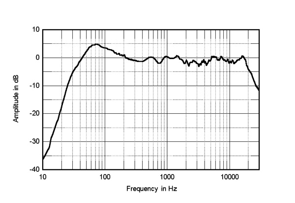
Hence the total response is in fact a combination of three tests, the farfield which is viewed as the correct phase, then a nearfield measurement whereby the microphone is with 1/10th the diameter of the cone, this gives us a pretty good 2Pi response, but it does have a downside and that 150 Hertz bump is a proximity effect. Finally we have the third measurement which is the port. Now these three are merged into a single response using the tools in my Audiomatica Clio software.
Let me give you an example from John Atkinson's measurements for Stereophile and not the following is very common:
Here is his explanation:
"The trace below 300Hz shows the sum of the nearfield woofer and port outputs, taking into account acoustic phase and the different distance of each radiator from a nominal farfield microphone position. The rise in response in the upper bass is due almost entirely to the nearfield measurement technique, the Gold 300's reflex tuning being maximally flat." John Atkinson
So whenever you see this showing up in measurement, just be aware that the bum is exaggerated. But it looks like the port nearfield measurement is the problem, considering this is showing up at an even lower frequency.
Last edited:
I guess so.
Joe used nearfield measurement for LF and farfield measurement for MF/HF.
He merged the measurements into a complete picture.
Correct!
.
I still don't understand the 150 Hz peak. I don't see how the proximity effect would be relevant here, as it does not happen with omni mics.
The Stereophile example is different. It shows a steady rise in the nearfied SPL response towards lower frequencies, until it reaches the bass cut off. This is the typical design approach taken in order to compensate the baffle step that occurs in the far field. This is different to the 150 Hz peak seen in the Elsinore curve.
Note that combining farfield measurements of the woofer and the port can be tricky, and merging them to the farfield curve is also not always straight forward. I therefore prefer the mic-in-box method, which directly yields the combined output of the woofer and the port, and it is easy to accurately convert its SPL level to the 2pi farfield.
Maybe it is a standing wave mode of the enclosure.
An inner height of 110 cm will give a ~ 150 Hz mode when not damped properly.
An inner height of 110 cm will give a ~ 150 Hz mode when not damped properly.
I still don't understand the 150 Hz peak. I don't see how the proximity effect would be relevant here, as it does not happen with omni mics.
It does happen with omni mics. There are heaps of measurements by John Atkinson's Stereophile and they are all done with omnis. I use omnis. I suggest you read JA's measurements on nearly a thousand loudspeakers for Stereophile and maybe all of them are online now? He refers to it quite often, also as to what mics he uses.
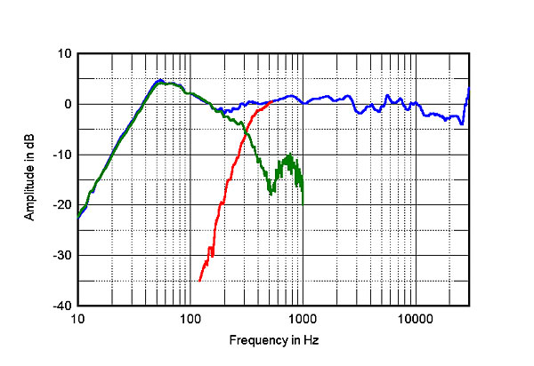
Below is an omni measurement of a Magico speaker:
His comments:
"The impedance traces suggest that the sealed enclosure is tuned to 34Hz. The two woofers behave identically, and their summed output is shown as the green trace in fig.2. The crossover to the midrange unit (red trace) appears to be set at 300Hz, and the broad peak in the midbass will be almost entirely due to the nearfield measurement technique, which assumes a 2pi (half-spherical) acoustic environment for the drivers. This peak aside, the –6dB frequency is just below 30Hz, which means that with the slow, 12dB/octave rolloff below the tuning frequency that is typical of a sealed enclosure, and the typical amount of boundary reinforcement or "room gain," the S5 Mk.II's output will extend to 20Hz. The Magico's upper-frequency farfield output, averaged across a 30° horizontal window centered on the tweeter axis (fig.3, blue trace above 300Hz), is impressively even overall, though with slight depressions in the presence region and in the top octave before the ultrasonic peak, due to the tweeter's primary dome resonance. Note, however, that this resonance lies above the 30kHz limit of this graph.”
With a farfield measurement, also with an omni, the peak disappears with the same speaker:
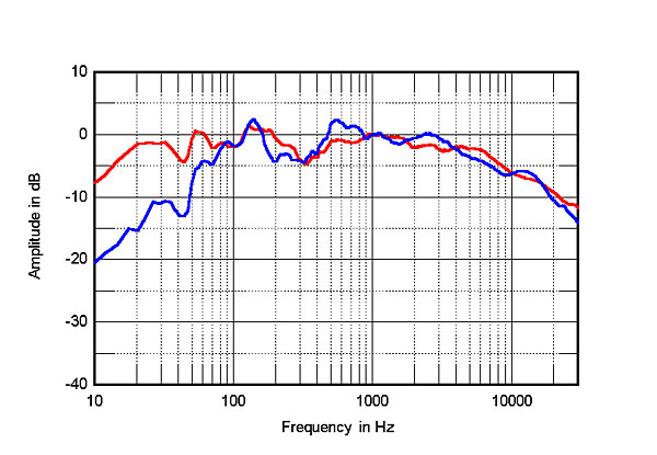
Only look at the RED trace, the other is another speaker entirely.
Re the Elsinore, the 150Hz peak also disappears with any farfield measurement using RTA 1/6th Octave with Pink Noise.
I am afraid it is what it is.
Here is another one, a B&W speaker:
Again that peak goes away as you move away.
.
Last edited:
I am quite sure Stereophile does not include baffle diffraction effects (baffle step curve) into nearfield measurement. It must be done to achieve good merging conditions, when corrected nf and ff curves overlap.
Though it can be difficult for Stereophile, I would not expect it to be problem for skilled diyer.
Though it can be difficult for Stereophile, I would not expect it to be problem for skilled diyer.
I am quite sure Stereophile does not include baffle diffraction effects (baffle step curve) into nearfield measurement. It must be done to achieve good merging conditions, when corrected nf and ff curves overlap.
Though it can be difficult for Stereophile, I would not expect it to be problem for skilled diyer.
Sorry, but what you are saying is confusing. That 'proximity' peak near 150 Hertz is not about the baffle step. Also, Stereophile (John Atkinson) only measures speaker as they are, so not sure what is supposed to be a problem?
As for an explanation of JA's measurements including a decent length of discussion on the proximity problem in nearfield capturing:
Loudspeaker Measurements Explained, John Atkinson, Stereophile Editor
Particularly listen to what he says and show from 17 minutes and 30 seconds into the video.
In fact at 20 minutes and 25 seconds, he shows an example that also have a 150 Hertz peak. As you will note, the peak can occur as low as near 60 Hertz and up to 150 Hertz and a bit. It is almost near impossible to predict just where and to what degree (2-6dB) it will show up. Just be aware, as John says, that correcting it may actually be worse and better just know what is happening and not loose to much sleep over it.
Similarly, when using microphones on say, voices, we note that at a distance the voice has less body, but as we get the mic closer, the body comes back and if the mic is too close and overdone, it can sound thick and not nice - unless of course that is what you want (did anybody mention rock singers?).
Also, something similar happens when recording acoustic pianos... and so on.
Last graph in #2652 is definitely result of nf plus ff merging. The bump around 100hz is result of the fact they did not include bafflestep curve. Merging point 300hz is clear.
Like Joe says, Stereophile measures speakers with the built in XO’s, so the speaker XO would include corrections for bafflestep losses (usually a high shelf attenuation filter circa 800Hz to 1kHz or higher for typical 10in to 12in wide speaker baffles). I am not sure what you mean by “they did not include bafflestep”? 150Hz bump is way too low to be a bafflestep effect unless your baffle is like 3ft wide.
I have not experienced a proximity peak in my measurements, but I never am closer than 0.5m - probably where it’s no longer an issue.
Perhaps this proximity effect should show up in a simulation of a speaker if I put the mic real close like 4in away?
I have not experienced a proximity peak in my measurements, but I never am closer than 0.5m - probably where it’s no longer an issue.
Perhaps this proximity effect should show up in a simulation of a speaker if I put the mic real close like 4in away?
Last edited:
Of course sterephile measures with crossover. I am saying that their graph, though looking like one measurement, is result of nf and ff stitching. NF part shows response to half space. FF part to full space. To obtain true full space response valid from low frequencies, one has to apply bafflestep curve to nf response. Pleade do not confuse this with baffle step compensation designer has to implement in crossover. Refer to Jeff Bagby white paper he did to provide manual for his excel sheet. Or try merge nf anf ff in Vituix cad, with or without crossover, nf and ff responses do not overlap well in ovelap region if bafflestep curve is not included to nf before merging. This is routine for anybody designing loudspeakers and working with nf plus ff measurements.
Joe, how did you obtain LF part of elsinores response?
Joe, how did you obtain LF part of elsinores response?
I am not sure what you mean by “they did not include bafflestep”?
I think what he means is that a nearfield mesurement does not see the bafflestep that happens when the box is in a room and you are far-field. As humans we do hear the bafflestep and that is typiclly 2-6 dB and where it happens will be somewhat dependent on the bffle width.
dave
Like Joe says, Stereophile measures speakers with the built in XO’s, so the speaker XO would include corrections for bafflestep losses (usually a high shelf attenuation filter circa 800Hz to 1kHz or higher for typical 10in to 12in wide speaker baffles). I am not sure what you mean by “they did not include bafflestep”? 150Hz bump is way too low to be a bafflestep effect unless your baffle is like 3ft wide.
Well summed up. You did it better than I did. 😀
I have not experienced a proximity peak in my measurements, but I never am closer than 0.5m - probably where it’s no longer an issue.
Perhaps this proximity effect should show up in a simulation of a speaker if I put the mic real close like 4in away?
Yep, that is why it does show up, certainly not at 0.5 metre. Even 4" might not show the bump, but in other respects, it will be a flawed measurement - but not necessarily a useless one. All measurements show at least something.
What JA would be doing is following the rule of D. B. Keele, that a microphone distance be less than 0.11 times the effective radius of the driver results in an error of less than 1dB. So with a typical 6.5" driver with a radius of about 60mm of the SB driver, that means about 6mm or 1/4". The accuracy of 1dB should work with the farfield measurement and using the equation required to adjust the level (attenuation) of the nearfield to the farfield. It should also then, using merging, show the diffraction loss/step. At least in theory, but in practice the merging takes some experience to do, IME. The bump artefact is a negative though, but we know about it, isn't that the most important part?
For those who want to read up on this, it is worthwhile to get Joseph D'Apopolito's book "Testing Loudspeakers, if they haven't already got it.
I think what he means is that a nearfield mesurement does not see the bafflestep that happens when the box is in a room and you are far-field. As humans we do hear the bafflestep and that is typiclly 2-6 dB and where it happens will be somewhat dependent on the bffle width.
dave
That's right, there is no baffle step recorded in the nearfield, only in the farfield.
But somehow a discussion where somebody (rightly) brought up the issue of the 150Hz bump, became conflated with what is a separate, but nonetheless fascinating, the topic of baffle step. But this is the job of the designer and not somebody like John Atkinson who measures the speaker as a total design.
Joe, how did you obtain LF part of elsinores response?
Pretty much following the text books. Read D'Appolito's book, it conforms with Keele's method. It is a combination of farfield at 2 metres (not the usual 1 metre) to get better phase matching when designing the Xover. Then a nearfield about 6mm on the cone of the driver, finally the port at the rear of the box. The farfield should show the baffle step, the nearfield does not. So these have to be merged to show that step. But the nearfield of the driver and the port are summed, not merged.
Of course sterephile measures with crossover. I am saying that their graph, though looking like one measurement, is result of nf and ff stitching. NF part shows response to half space. FF part to full space. To obtain true full space response valid from low frequencies, one has to apply bafflestep curve to nf response. Pleade do not confuse this with baffle step compensation designer has to implement in crossover. Refer to Jeff Bagby white paper...
I was not confused, the discussion was about the 150Hz bump and the topic got confused with baffle step issues.
BUT: You are quite right, but his, Atkinson's, farfield measurement is derived/measured in a different way. Please follow my explanation...
Except for a single driver (bass), he does the farfield at 50" of the entire box, and because he wants the total system response, he puts the driver on a rotary table and averages out over a 50 degree arc. He then does the nearfield of the driver (and the port if used) the same way as described above.
I have been reading John Atkinson's speaker measurements even going back to his Hi-Fi News days when he teamed up with Martin Colloms. Also his many hundreds of speakers test (near 1000?) for Stereophile.
But may I reiterate something above? What Atkinson tries to do is get his frequency response to reflect something like the power response of the total speaker. Using that rotary table and publishing his measurements, he has influenced the bulk of high-end speaker designers around the world, that a speaker should measure overall reasonable flat when he is using that test. This I believe has been a good thing. They know they can't just come up with a speaker that produces a flat on-axis response, they have to consider the off-axis as important - and that it isn't just about the measurement, but about getting the speaker to sound right.
Now the designer who has to design the system and especially the Xover, here I am referring to myself, to use computer modelling I have to get the relative phase between the drivers right. So I can't use a rotary table and have to choose where I put the microphone for the farfield very carefully. The farfield has the phase information, the nearfield does not.
Set up four models, change the Xover in one, make the same in the other three and plot. Put more emphasis on the off-axis as being more important.
It shows a 1 metre example, but only because it exaggerates the numbers and that at 2 metres the numbers, and hence the phase, will be different.
I hope I am getting this across? I need to capture those relative phases by not moving the microphone, or else I can't use computer modelling to assist me in doing the Xover. The microphone must be fixed! But somebody like Atkinson has to do the opposite in order to get the total averaged response right.
But I do think we have conflated separate issues. The 150Hz bump is one thing, the capturing of farfield and nearfield and capturing the baffle step is another thing. And then what are the aims and purposes of those measurements, as they are different to a designer than they are to a reviewer/tester.
Whew!
Cheers, Joe
Last edited:
Maybe it is a standing wave mode of the enclosure.
An inner height of 110 cm will give a ~ 150 Hz mode when not damped properly.
Of course, now that you mention it this makes a lot of sense!
...when using microphones on say, voices, we note that at a distance the voice has less body, but as we get the mic closer, the body comes back and if the mic is too close and overdone, it can sound thick and not nice - unless of course that is what you want (did anybody mention rock singers?).
Also, something similar happens when recording acoustic pianos... and so on.
I believe that now your are referring to the proximity effect, which is a low-frequency boost that happens with (directional!) pressure-gradient microphones. It does NOT happen with (omnidrectional) measurement microphones. See here: Proximity effect (audio - Wikipedia)
Note that the proximity effect creates a low-frequency boost, NOT a peak in the SPL curve.
I think what he means is that a nearfield mesurement does not see the bafflestep that happens when the box is in a room and you are far-field. As humans we do hear the bafflestep and that is typiclly 2-6 dB and where it happens will be somewhat dependent on the bffle width.
+1. And baffle step is something else than proximity effect.
The 150Hz bump is one thing, the capturing of farfield and nearfield and capturing the baffle step is another thing. And then what are the aims and purposes of those measurements, as they are different to a designer than they are to a reviewer/tester.
No matter if you are a designer or a tester, you want to know how the speaker works.
Overall, I see a few new questions regarding the low-frequency acoustic behaviour of the Elsinores coming up:
- If the 150 Hz peak really is due to a standing wave between the top and the bottom of the box, how does the electrical impedance curve look at this frequency? Such resonance effects are usually visible in the impedance curve. Joe, can you zoom in to the impedance curve at the relevant frequency range and show this here? Make sure there is no smoothing applied to the impedance curve.
- The "proximity effect" explanation on the Elsinore website for the 150 Hz peak does not seem to make much sense (the proximity effect does not create a peak, and it does not happen with typical measurement microphones). I guess it would be better to remove this from the website.
- As Joe mentioned in an earlier post, the low-frequency part of the SPL curve shown on the website reflects the sum of nearfield measurements taken from the woofer(s) and the port. Adding the low-frequency baffle step loss means that the farfield SPL curve would show up to 6 dB lower SPL in the bass. This means the farfield SPL response would be rather unbalanced. For a balanced far-field bass SPL, the nearfield curve should show a rise towards low frequencies as in the Stereophile example above.
- Joe, you mentioned the 150 Hz peak goes away if you move the microphone further away from the speaker. How did you do this measurement? You'd need a FFT frequency resolution of about 50 Hz to be able to observe the peak. This means you'd need a 20 ms long anechoic impulse response. Did you do such measurements in an anechoic chamber, or outoors on a very high stand? (the speaker would need to be about 3.5 m above the floor to get 20 ms of anechoic data)
- Home
- Loudspeakers
- Multi-Way
- The "Elsinore Project" Thread