And how will this cicuit look like ?
Not worthwhile pursuing this.
The solution to the current problem has already been provided
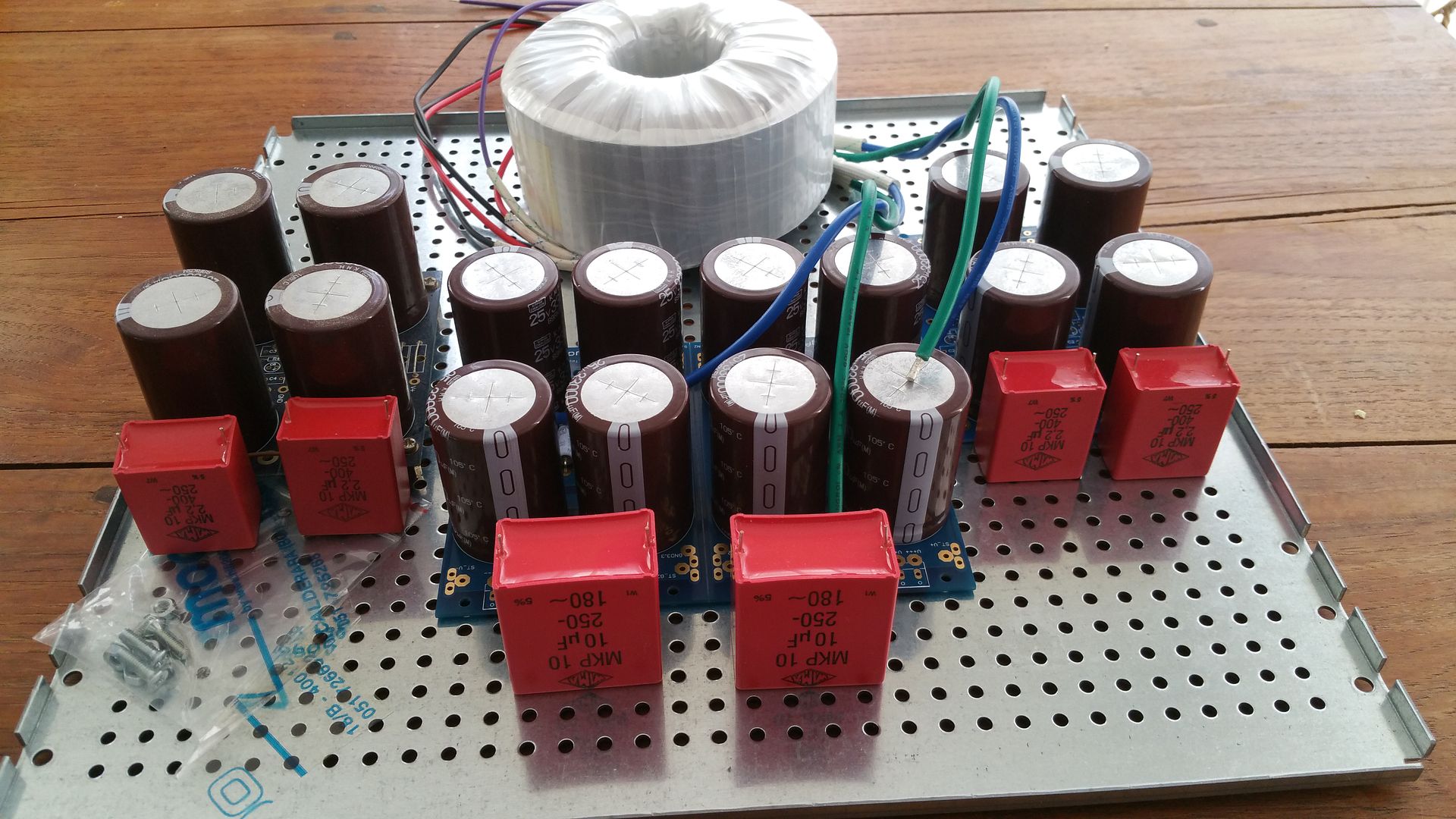
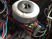
Preparing the powersupply. Making sure everything fits.
Decided to go for a sensible amount of madness.
Decided to go for a sensible amount of madness.
132000uF per rail on main bank feeding separate supplies of 66000uF per rail.Nice , Are you using separate power supply for each channels ?.
So each channel has an independent supply feeding off main supply.
Nice , Are you using separate power supply for each channels ?.
Not unless he's doing Mono Blocks, he has stated he is using 5U box, that is a 5U floor pan I believe....will be Way adequate.
Russellc
Interesting, I've seen plenty of supplies dual mono from the transformer forward, first time I've seen a combination...So will there be 4 rectifier bridges I assume?
Russellc
Russellc
Is there a reason why you just didnt use another power supply board and do standard dual mono? (from the transformer forward)
Russellc
Russellc
132000uF per rail on main bank feeding separate supplies of 66000uF per rail.
So each channel has an independent supply feeding off main supply.
Interesting.
D
Deleted member 24284
I had thought that one major reason for the mono block configuration is to avoid having to use any speaker cable, as I can just put one amp next to each speaker. If I do that, then at most I can share a transformer between the two amps. I cannot share filter caps.
I had thought that one major reason for the mono block configuration is to avoid having to use any speaker cable, as I can just put one amp next to each speaker. If I do that, then at most I can share a transformer between the two amps. I cannot share filter caps.
No not at all. That is just a benefit on the side
Normally I do completely separate banks, but sometimes there is not enough room and it is a little more expensive.Is there a reason why you just didnt use another power supply board and do standard dual mono? (from the transformer forward)
Russellc
If you go back and carefully inspect Nelson's stereo F6 supply (very carefully) you will notice the RC is independent for each channel.
I am just doing a twin turbo version of Nelson's supply.
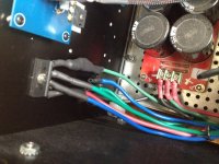
Thank you . What is the benefit of using those 10uf MKP s there ? and what is the specification of that Antek Transformer ?.
Thank you . What is the benefit of using those 10uf MKP s there ? and what is the specification of that Antek Transformer ?.
1) Electrolytics have increasingly higher impedance with increasing frequency.
Film caps have much lower impedance, so filter out higher frequency noise more effectively. I have a stack of them so may as well put them to use.
2)Antek AS-4218, 400VA with magnetic and electrostatic shielding
F6 in BTL/Bridge Style Configuration: Finished and running for about 3 months
Hi all again,
Some months ago I had an idea for building a F6 amplifier, but using 2 boards per channel, one for positive and other for the negative signal of a XLR output from my preamplifier, after a lot of time waiting the parts, I can say that it works and sound wonderful.
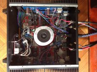
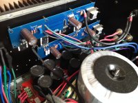
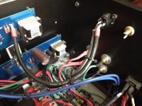
The build was done using a 5U case from Modushop, each channel has its own transformer and power supply (each with 8 x 22.000uF caps) that feeds the 2 x F6 boards, there are also a soft start circuit and a BTL speaker protection circuit at the output.
All transistors, resistors and caps on the F6 boards where carefully matched from a large sets. My initial concerns about output offset was just concerns, after adjusting bias to .7 volts across R2, adjusting offset using P1, the relative output offset was stable near to 0.5 mV and the offset to GND was near to half of the relative offset. The other concern was about heatsinks temp, having 4 x F6 boards inside the same case is really a crazy idea, but the dissipation capacity of the heatsinks was enough to keep it under 60C, even with 26C ambient temp.
The construction is ugly, a lot of internal wire connecting the stuff, the transformers are mounted one over the other, It’s really difficult to adjust bias and offset because the position of boards, I had to use a plastic screwdriver to avoid a short circuit. I promise as soon I had the opportunity I will change the single case for 2 monoblock cases.
The sound is great, really great!!!, thanks to Mr. Pass for sharing your designs with the DIY community, and also all others that share knowledge on how this could be made.
Alejandro
Hi all again,
Some months ago I had an idea for building a F6 amplifier, but using 2 boards per channel, one for positive and other for the negative signal of a XLR output from my preamplifier, after a lot of time waiting the parts, I can say that it works and sound wonderful.
The build was done using a 5U case from Modushop, each channel has its own transformer and power supply (each with 8 x 22.000uF caps) that feeds the 2 x F6 boards, there are also a soft start circuit and a BTL speaker protection circuit at the output.
All transistors, resistors and caps on the F6 boards where carefully matched from a large sets. My initial concerns about output offset was just concerns, after adjusting bias to .7 volts across R2, adjusting offset using P1, the relative output offset was stable near to 0.5 mV and the offset to GND was near to half of the relative offset. The other concern was about heatsinks temp, having 4 x F6 boards inside the same case is really a crazy idea, but the dissipation capacity of the heatsinks was enough to keep it under 60C, even with 26C ambient temp.
The construction is ugly, a lot of internal wire connecting the stuff, the transformers are mounted one over the other, It’s really difficult to adjust bias and offset because the position of boards, I had to use a plastic screwdriver to avoid a short circuit. I promise as soon I had the opportunity I will change the single case for 2 monoblock cases.
The sound is great, really great!!!, thanks to Mr. Pass for sharing your designs with the DIY community, and also all others that share knowledge on how this could be made.
Alejandro
Attachments
P1,P2 pots setting procedure
Hi,
A newbie question on setting the bias and offset pots before soldering.
Do I have to set the offset pot in middle position - 2.5k and set the bias pot to 0 before soldering onto the store PCB ? I'm going to run a bulb for the first time start up.
Thanks in advance
Albert
Hi,
A newbie question on setting the bias and offset pots before soldering.
Do I have to set the offset pot in middle position - 2.5k and set the bias pot to 0 before soldering onto the store PCB ? I'm going to run a bulb for the first time start up.
Thanks in advance
Albert
Hi,
A newbie question on setting the bias and offset pots before soldering.
Do I have to set the offset pot in middle position - 2.5k and set the bias pot to 0 before soldering onto the store PCB ? I'm going to run a bulb for the first time start up.
Thanks in advance
Albert
That is definitely one approach that will work.
If you have 25 turn pots and using a 6.2V Zener, then I would set both pots to centre or you will be bloody turning forever. Hahaha
What Zeners are you using
- Home
- Amplifiers
- Pass Labs
- The diyAudio Firstwatt F6