No.... couldn't resist and ordered the boards 😀
You'll love it! It's a fantastic amp.
Alas I'll have to wait for the package since I only have the wired transformer.
This looks very exciting. I'm looking forward to hearing more from those lucky
early builders of this amp.
Cheers,
Dennis
This looks very exciting. I'm looking forward to hearing more from those lucky
early builders of this amp.
Cheers,
Dennis
With no thought about wandering bias I've been listening for the last week with bias set at 1.7ish amps.
this is indeed an awesome amp.
It seems to have a more precise sound stage than the other F amps and is equally, if not more detailed than the others. So far I like it as much as my favourite 2A3...time will tell. I'm going to try it with my full range electrostats next.
I've just posted some thoughts on smps power supplies on Wuffwaff' thread (http://www.diyaudio.com/forums/pass-labs/275183-silent-transformers-europe-2.html) as he is suffering from noisy toroids. It occurred to me that it may address the wandering bias issue I have that is caused by fluctuating mains. I'm currently testing one of the smps power supplies and so far the output seems rock solid with a wandering mains input. More details when I have more data.
If other UK builders are having the same issues with their mains then this may be a cost effective solution, although if the SQ is not suffering then I suppose why bother worrying.
Ed
Yes, always.
Ok cause it is not marked on the board. I was guessing.
this is indeed an awesome amp.
It seems to have a more precise sound stage than the other F amps and is equally, if not more detailed than the others. So far I like it as much as my favourite 2A3...time will tell.
This amp has me wondering if a healthy dose of the 'tube sound' is actually transformers in the signal path. It sounds divine. I am really enjoying this amp.
I'm currently testing one of the smps power supplies and so far the output seems rock solid with a wandering mains input. More details when I have more data.
Fantastic! I'm looking forward to hearing about successes with a SMPS for our purposes.
HI guys, a question on bias please. I am using teabags boards and IRFP 240s. do I measure the bias voltage across gate and source and if so what voltage should it be set at? At 1.2 volts following nelsons schematic it shows 1.2v across gate and source but I assume this is for semisouths.
I can get the voltage higher, went up to 3 volts but the IRFPs did not get hot at all.
Any thoughts or suggestions appreciated.
I can get the voltage higher, went up to 3 volts but the IRFPs did not get hot at all.
Any thoughts or suggestions appreciated.
Bias current is measured across the source resistors. About an amp to start off. .5v across the .47ohm source resistor, or .55V across the .56ohm resistor.
IRF240 usually need 4.2-4.5 Vgs to turn on. What LED/Zener are you using for bias?
IRF240 usually need 4.2-4.5 Vgs to turn on. What LED/Zener are you using for bias?
Thanks 6l6 OK, using .47 source resistor across should give me .5v.
Sorry, this is going to sound really stupid but still beginner. Does this means I put on terminal of my multimeter on one side of the resistor and the other terminal to the other side of the resistor to measure voltage across? let me try now
I have two led blue 3 volt led following teabags plan. .
Sorry, this is going to sound really stupid but still beginner. Does this means I put on terminal of my multimeter on one side of the resistor and the other terminal to the other side of the resistor to measure voltage across? let me try now
I have two led blue 3 volt led following teabags plan. .
The only stupid question is the one not asked...
🙂
Yes, place the multimeter in DC volts and measure across the resistor.
Two blue LED should be enough to get the IRF240 to turn on.
🙂
Yes, place the multimeter in DC volts and measure across the resistor.
Two blue LED should be enough to get the IRF240 to turn on.
nope, something must be wrong.... I adjusted both pots to full travel and got zero across source resister, and offset went to 1 volt from 20 mv.
Thanks 6l6 I will try again when I get back tommorrow on the other channel. My wife is waiting for her date tonight. Cheers and thanks,
to be precise ...... what we are measuring is Iq , meaning quiescent current
what we are usually writing as bias is not exact biasing voltage (precisely Ugs needed for Iq) , but some other voltage - say that one across source resistor , resulted from Iq flowing through it.
when having enough under the belt , we are ignoring those imprecise terms , knowing what we are talking about .... but , when someone is here with lesser mileage , we need to be precise

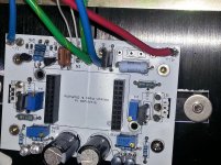
Thanks very much, I took a photo and attached.
My mistake was the resistor I believe. In the schematic, Source Resistor is R13 and R 14, resistor from source 0.5r and not r8 and r7 which is 47.5r. I was originally measuring across r8 and r7 and getting nothing.
Now I have .505 volts dc across r13 and .8mv offset (between speaker terminals).
After ten minutes I get about 52 degrees c or so on the IRFP240s and the heatsink is slightly warm so I guess all is good.
I will hook up the second channel now and see what I get.
Sorry guys I had a bit of a brain bleed there and forgot what was what. Thanks for the help with the mileage Zen Mod and appreciate the help 6l6 and vid.
Attachments
- Home
- Amplifiers
- Pass Labs
- The diyAudio Firstwatt F6